Ricoh BE-C1 D046 Скачать руководство пользователя страница 207

• This setting must be selected and displayed before you can do the installation procedure.

Seal Check and Removal

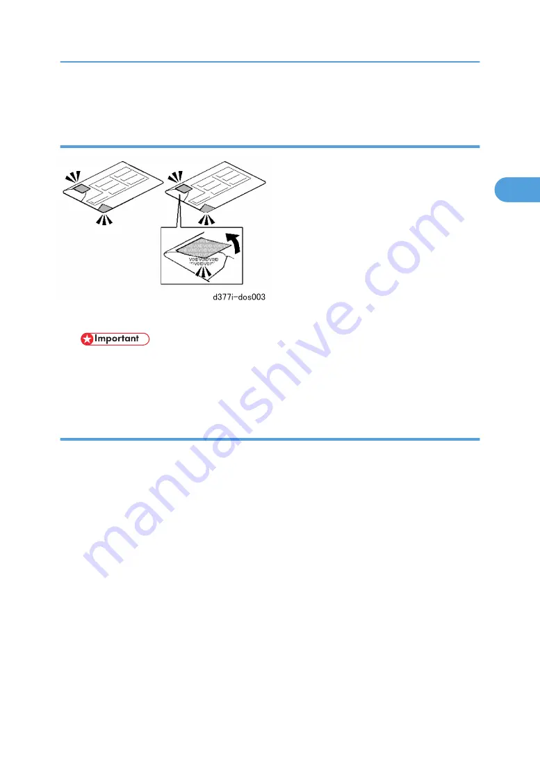
1. Check the two seals and confirm that they are firmly attached.

• If you see "VOID" on the tapes this means that the seals have been disturbed. If the "VOID"

notations are visible, do not use the SD card for this installation. Contact your sales division.

2. Remove the seals. The silver "VOID" notations become visible only after you have removed the seals.

Installation Procedure

Before doing the procedure, turn off the main power switch and unplug the machine from its power source.

1. Make sure that the machine is switched off and disconnected from its power source.
2. Disconnect the network cable.
3. Turn the main power switch on.
4. Turn the operation switch and main power switch off.
5. Remove the SD card slot cover (

x1).

6. Check the security tape on the wrapping.

• If you see "VOID" on the security tape this means that the tape has been disturbed.
• If the "VOID" notations are visible, do not use the SD card for this installation. Contact your sales

division

7. Remove the security tape from the SD card wrapping.
8. Insert the DOS SD card into Slot 1.

MFP Options

205

2

Содержание BE-C1 D046

Страница 1: ...Model Be C1 Machine Code D046 D049 Field Service Manual August 2008 Subject to change...

Страница 2: ......

Страница 3: ...ng unit become extremely hot while the machine is operating Be careful to avoid touching those components with your bare hands 7 Always connect the power cord directly into a wall outlet Never use an...

Страница 4: ...ancewithlocalregulations These are non toxic supplies 3 Dispose of replaced parts in accordance with local regulations 4 When keeping used lithium batteries in order to dispose of them later do not pu...

Страница 5: ...paper feed In this manual Horizontal means the Main Scan Direction and Vertical means the Sub Scan Direction relative to the paper feed direction Switches and Symbols Where symbols are used on or near...

Страница 6: ...serious injury A Caution indicates a potentially hazardous situation Failure to obey a Caution could result in minor or moderate injury or damage to the machine or other property Obey these guideline...

Страница 7: ...e cleaning blade in contact with the drum 4 After moving the machine to a new location always re install the leveling shoes under the casters of the machine Points to Confirm with Operators At theendo...

Страница 8: ...other small metallic objects to fall into the machine Caution operators about storing extra toner cartridges To prevent clumping on one end of the toner cartridge it should always be stored horizontal...

Страница 9: ...onment 17 Space Requirements 18 Machine Level 21 Power Source 21 Installation Procedure Guide 22 Main Machine D046 D049 27 Accessory Check 27 Installation Procedure 29 Roll Feeder Type 7140 D394 47 Ac...

Страница 10: ...6 Before You Begin 188 Printer Option Type W7140 D396 192 Scanner Option Type W7140 D397 194 IEEE 1284 Interface Board Type A B679 17 Centronics 196 IEEE 802 11a g Interface Unit Type J K D377 01 02 1...

Страница 11: ...ers 275 CIS 281 Exposure Glass 287 Original Junction Gate Original Junction Gate Solenoid 290 Around The Drum 295 LPH LED Print Head 295 Charge Corona Unit 298 Quenching Lamps 300 Drum Development Uni...

Страница 12: ...Transport Belts 342 Gear Replacement 343 Fusing 345 Fusing Unit 345 Paper Junction Gate Solenoid Exit Sensor 349 FPDB Fusing Pressure Drive Board 349 Pressure Roller Thermistors 350 Hot Roller Center...

Страница 13: ...03 Breaker Switch 404 Other 406 Ozone Filter 406 Used Toner Bottle Cleaning 406 Important Adjustments 409 LPH Adjustment with SP Codes 409 LPH Density Adjustment with SP Codes 412 Image Position Magni...

Страница 14: ...ors Manually 432 New Debug Log Codes 432 Printing an SMC Report 434 Initialize All SP Settings 435 Calibrating the Touch Panel 436 Calibrating the Touch Panel 436 Software Reset 437 Card Save Function...

Страница 15: ...Product Information Specifications See the Appendices for the following information Main Machine Specifications Printer Controller Specifications Scanner Specifications Peripheral Specifications 13 1...

Страница 16: ...Overview See the Appendices for the following information Machine Layout Mechanical Component Layout Drive Layout With Optional Roll Feeder Original Copy Paper Paths 1 Product Information 14 1...

Страница 17: ...Machine Codes Peripheral Configurations For the machine codes and peripherals configuration please refer to the Appendices Machine Codes Peripheral Configurations 15 1...

Страница 18: ...46 D049 B188 Developer TYPE 30W BLACK TYPE 16W BLACK Toner New cartridge Same cartridge as B010 B125 B286 Printer Option GW Type W7140 External Type RW 7140 External Type RW 480 Scanner Scanner unit c...

Страница 19: ...Room air should turn over at least 3 times per hour 5 Ambient Dust Less than 0 075 mg m3 6 If the installation place is air conditioned or heated place the machine as follows Where it will not be subj...

Страница 20: ...Space Requirements Minimum Space Requirements A Front 1 000 mm 39 B Back 600 mm 23 6 C Right 600 mm 23 6 D Left 600 mm 23 6 Height 450 mm 18 2 Installation 18 2...

Страница 21: ...Configuration 1 Main Machine D046 D049 Standalone Configuration 2 Main Machine Folder FD6500A B889 Preparation 19 2...

Страница 22: ...Configuration 3 Main Machine Folder FD6500B B890 2 Installation 20 2...

Страница 23: ...level using a carpenter s level Power Source The machines must be installed in a building or facility equipped with a protective device such as a circuit breaker as the machine relies on such devices...

Страница 24: ...ng Folder FD6500A B B889 B890 1 Input Voltage Level 120V 60Hz More than 2 5 A for the U S A version 220 to 240V 50 60Hz More than 1 2 A for the Europe China version 2 Permissible Voltage Fluctuation 1...

Страница 25: ...e 7140 D394 or Paper Cassette Type 7140 D395 1 Install the main machine p 27 2 Install Roll Feeder D394 p 47 or Paper Cassette D395 p 64 You must install the roll feeder or paper cassette before insta...

Страница 26: ...easier to access the controller box SD card slots and board slots before the fan folder is installed If the fan folder has already been installed disconnect folder FD6500A B and pull it away from the...

Страница 27: ...in machine p 27 2 Install the roll feeder p 47 or Paper cassette p 64 3 Install the MFP options p 186 4 Remove the tapes and shipping materials from the Folder FD6500A B889 5 Remove the tapes and ship...

Страница 28: ...2 The manual feeder and bridge unit are pre installed on the fan fold unit 5 Dock the fan fold unit to the back of the main machine 6 Remove the tapes and shipping materials from the Cross Fold Unit B...

Страница 29: ...against the following list No Description Q ty 1 Cloth Exposure Glass 1 2 Paper Holder 4 3 Operating Instructions Holder 1 4 Rear Copy Tray Guide 3 5 Rear Copy Tray 3 6 Guide Mylar Curved 2 7 Guide M...

Страница 30: ...riginal Tray 3 15 Original Guide 1 16 Original Guide Plate 1 17 Step Screws 2 18 Round Head Screws M4 x8 Original Tray x2 each 6 19 Tapping Screws M3 x 6 5 20 Grommets 6 21 Ferrite Core 1 Because the...

Страница 31: ...ith lifting equipment a fork lift The machine weighs approximately 230 kg 507 lb If a fork lift is not available at least 4 people one on each corner of the machine are needed to lift it from the pall...

Страница 32: ...ure The position of the operation panel can be adjusted to reduce reflection on the operation panel display 4 If you want to adjust the position remove the screws x3 5 Raise or lower the operation pan...

Страница 33: ...move the packing B 11 Open the upper unit A 12 Pull out the red tape and remove the drum protection sheet B Pull the red tape out slowly and carefully to prevent damage to the cleaning unit entrance s...

Страница 34: ...a level at A and B 2 Make the machine level by turning the bolts C on the machine s four feet The gap D must be less than 2 mm for the bolt to clear the roll feeder option when the feeder is opened an...

Страница 35: ...numbers when you input them later with SP2801 2 and 3 3 Open the first 1 kg pack of developer C and pour it into the development unit Slowly add the developer from the first pack into the development...

Страница 36: ...joint If the joint does not turn do the procedure again Tell the customer how to prepare a toner cartridge for installation If toner is not loosened before the toner cartridge is installed the custom...

Страница 37: ...e developer evenly inside the development unit 10 Wait about 22 seconds until the machine stops 11 Turn the operation switch off 12 Turn the main power switch off 13 Open the upper unit 14 Open the to...

Страница 38: ...ne to warm up 3 Enter SP mode Press the Clear Modes key Enter 1 0 7 Hold down Clear Stop for more than 3 seconds Touch System SP 4 Do SP2801 2 and 3 to enter the lot numbers Use the soft keyboard on t...

Страница 39: ...d push 7 Push Execute The machine enters the drum set mode and dusts the drum with toner 8 When the message prompts you that the operation is finished touch Exit 9 Open the upper unit A and confirm th...

Страница 40: ...P mode Sample Copies 1 Load some roll paper in the machine For loading instructions see the decals on the top edge of the roll feeder front cover 2 Make some copy samples Emblem Panel Brand Set D046 o...

Страница 41: ...Copy Tray 1 Attach the front copy tray A Original Trays Only three original trays are provided The trays can be installed on top of the machine Top Exit or at the rear Rear Exit Main Machine D046 D049...

Страница 42: ...A they are identical 1 Attach B Original guide plate C Original guide 2 Set upper original guide A 3 Set original tray B in the center This is the tray with the original guide plate and original guide...

Страница 43: ...oint of operation Before feeding large originals larger than A0 pull the original guide plate A out and pull the original guide B forward Original Trays Rear Exit 1 Attach an original tray mylar A to...

Страница 44: ...Trays and Mylars 1 Remove the bottom screws of the rear cover A x4 Do not discard these screws 2 Set the step screws in the rear cover A x2 3 Hang the support bracket B on the step screws 2 Installat...

Страница 45: ...bracket A x3 5 Fasten the rear copy tray holder B x6 Use the four screws removed earlier from the bottom edge of the rear cover 6 At the rear attach A Guide mylar strips x3 B Curved mylars x2 Main Ma...

Страница 46: ...into the holes in the support bracket C and rear copy tray holder D Testing the Breaker Operation 1 Make sure that the main power switch is off 2 Check the power cord of the copier and make sure that...

Страница 47: ...the O position Make sure that the power cord is securely connected to the power supply Push the test button again Ifthebreakerswitchdoesnotsnapdowntothe O position thebreakerswitchmustbereplaced 5 Rai...

Страница 48: ...2 Fasten the ferrite core to the end of the LAN cable connector about 4 5 cm from the end nearest the machine 3 Attach the LAN cable A to the LAN connector B 2 Installation 46 2...

Страница 49: ...their quantities against the following list No Description Q ty 1 Left Slide Rail 1 2 Right Slide Rail 1 3 Paper Holder 4 4 Positioning Pins 2 5 Drawer Connector 1 6 Cover Plates 2 7 Harness Clamp LWS...

Страница 50: ...he main machine power cord before starting the following procedure Before starting the installation insert the leveling shoes under the leveling feet and level the machine The machine is very heavy To...

Страница 51: ...Covers 1 Remove A Rear copy tray guides x3 B Rear copy tray x3 2 Remove A Rear copy tray holder x6 B Rear cover x3 C Right rear cover x6 Roll Feeder Type 7140 D394 49 2...

Страница 52: ...rear cover x7 F Left front cover x4 3 Remove tray cover A x2 Keep these screws to reattach the cover later 4 Remove the step screws B and discard them x2 5 Remove and discard these screws A Left side...

Страница 53: ...brackets x2 C Right side bracket x1 Controller Box 1 Top A Harness clamp screw x1 B Connectors and clamps x2 x6 2 Right side C Connectors x2 D FFC x1 3 Remove the controller box E x4 Roll Feeder Type...

Страница 54: ...4 Remove the inner cover A x2 Rails and Front Positioning Pins 1 Remove the used toner bottle A x1 2 Installation 52 2...

Страница 55: ...tall the right rail A and left rail B Step x 2 each x 8 each M4 x 6 3 Install the positioning pins A x 2 each M4 x 6 4 Lower the bolt B until it is level with the base plate Roll Feeder Type 7140 D394...

Страница 56: ...Drawer Connector 1 Loosen the screws on the connector bracket A x3 2 Set the drawer connector A in its slot at the rear of the machine 2 Installation 54 2...

Страница 57: ...3 On the left side fasten the drawer connector bracket A x4 4 Behind the connector of the upper roll feeder drawer A separate the connectors B x1 Roll Feeder Type 7140 D394 55 2...

Страница 58: ...connector which was separated in the previous step x1 7 Connect the harness from the lower drawer connector to the red connector A on the left side of the machine x1 8 Fasten the lower drawer connecto...

Страница 59: ...lamp x1 11 At the bottom fasten the thin harness red connector and ground wire B with the clamp x1 Flat Cable and Roll Feeder Tray 1 At the right rear corner inside the machine install two harness cla...

Страница 60: ...ss clamps A and B 3 Attach edging cover C 4 Remove flat cable A 5 Set the roll feeder B on the positioning pins C of the left and right rails 6 Fasten the tray to the rails D x 2 each M4 x 6 2 Install...

Страница 61: ...r roll feeder drawer completely 9 Pull out the flat cable A as far as it will reach 10 Set the cable in flat clamp B and C then close the clamps 11 Open the harness clamps x7 and flat clamp D 12 Close...

Страница 62: ...t A and right B 2 Very slowly push in the lower drawer A until it locks This positions the drawer correctly at the drawer connector at the rear and at the positioning pins at the left and right front...

Страница 63: ...4 Reattach the inner cover A x2 5 At the front with the drawer still closed tighten the roll feeder positioning brackets A On the left x2 B On the right x2 Roll Feeder Type 7140 D394 61 2...

Страница 64: ...ower front cover A x2 Use the screws removed from either end of the cover when you removed it 3 Attach the decal B 4 Fasten one cover plate 1 to the left side of the drawer x1 5 Attach the other cover...

Страница 65: ...ter Switch 1 The heater switch A for the roll feeder is at the rear left corner of the roll feeder 2 Switch on the roll heater if the humidity at the installation site is high Roll Feeder Type 7140 D3...

Страница 66: ...tion 1 4 Decal Warning A2 High Temperature 1 5 Guide Screws 2 6 Tapping Screws M4 x 8 6 7 Tapping Screws M3 x 8 4 8 Harness Clamps LWS 0711 5 9 Harness Clamps LWS 2218 2 10 Harness Clamp 1 11 Bushing...

Страница 67: ...Paper Cassette Type 7140 D395 65 2...

Страница 68: ...ssory pack B all tapes and shipping material Always turn the machine off and unplug the machine before you do any of the following procedures The cassette tray weighs 60 kg 132 lb At least two people...

Страница 69: ...copy tray guides x3 B Rear copy tray x3 2 Remove A Rear copy tray holder x6 B Rear cover x3 C Right rear cover x6 D Right front cover x4 E Left rear cover x7 F Left front cover x4 Paper Cassette Type...

Страница 70: ...2 Discard these screws 4 Remove the step screws B x2 Discard these screws Guide Screws Caution Decal Heater Harness 1 Put the guide screws A x2 in the holes 2 Attach the warning decal high temperature...

Страница 71: ...de the drawer 4 Attach the small bushing B to the hole 5 Insert the small end of the heater harness C through the grommet and pull it to the front 6 Close the harness clamps on the harness 7 At the le...

Страница 72: ...e D to remove slack 12 Close the harness clamps x3 Interface Harness 1 At the right rear corner attach the large bushing A 2 Thread one end of the interface harness B through the hole The white gray c...

Страница 73: ...four harness clamps A 5 Attach the long harness clamps B 6 Connect the harness A to CN235 and CN236 on the IOB x2 7 Put the harness in the clamps and close the clamps around the harness x6 Paper Cass...

Страница 74: ...et the cassette tray A in front of the copier 2 Connect the cassette tray interface connector B x2 3 With one person on each side of the tray lift the tray and slide it between the guide pin on the le...

Страница 75: ...lock pin B in the order that is shown by the numbers x2 each Insert the stud of each lock pin first on the left then on the right Check that all 6 holes are aligned correctly before you attach the scr...

Страница 76: ...and are M4 size 7 Pull out the roll feeder drawer A 8 Install the left cover plate B x1 9 Install the right cover plate C x1 10 Close the roller feeder drawer 11 Open the cassette drawer 2 Installati...

Страница 77: ...size decals C Tray Cassette Heater Switch 1 Turn on the tray cassette heater switch A if the humidity at the installation site is very high 2 To turn the cassette tray heater on Open the top drawer u...

Страница 78: ...41 This option cannot be used when Folder FD6500 A B B889 B890 is installed Accessory Check No Description Q ty 1 Base Strut Frame 2 2 Base Struts 2 3 Middle Struts 2 4 Tray Struts 2 5 Original Tray 1...

Страница 79: ...tion Procedure 1 Attach the following to the base struts A B Casters diameter 40 with stopper C Caster diameter 40 2 Assemble base stays D and base frame struts A Bolts x4 Washers x4 3 Attach caps E t...

Страница 80: ...4 Attach A Middle struts Bolts x4 Washers x8 Nuts 4 B Tray struts Bolts x4 Washers x8 Nuts x4 C Caps 5 Install the original tray A on the original tray stays x 6 2 Installation 78 2...

Страница 81: ...6 Attach the size decals 7 Attach A Original stoppers B Original guides Tray and Stacker Options 79 2...

Страница 82: ...cker B on the right 3 Hang the other stacker C on the left Multi Stacker Type 7140 D437 This option cannot be used at the rear when the following are installed Folder FD 6500 A B B889 B890 Original Ex...

Страница 83: ...Accessories No Description Q ty 1 Stacker Tray 1 2 Stoppers 2 3 Guides 2 4 Crosspieces 2 5 Tray Legs 2 6 Long Bolts M8x45 4 7 Allen Key 1 Tray and Stacker Options 81 2...

Страница 84: ...ss piece 1 to tray legs 3 and 4 Long bolts x2 Fasten cross piece 2 to tray legs 3 and 4 Long bolts x2 2 Note the F markings on the tray legs 1 and the stacker tray 2 The F marks must face toward the r...

Страница 85: ...rk on the stacker tray 1 over the F marks on the legs insert the arms of the stacker tray into the holes in the upright supports 2 5 Push down the stacker tray 3 completely so the holes 4 are aligned...

Страница 86: ...6 Reattach the knobs 1 Left knobs x2 2 Right knobs x2 7 Loosen the tray height adjustment knobs 1 Left knob x1 2 Right knob x 1 2 Installation 84 2...

Страница 87: ...n the height adjustment knobs 9 Install the tray At the rear for originals or copies or At the front for copies Original Rear Exit Follow this procedure to set the multi stacker tray to hold long orig...

Страница 88: ...tacker tray is on the same side as the F marks on the legs 2 Loosen the tray angle adjustment knobs on the right 1 and left 2 3 Adjust the angle of the tray 3 to the height of the original exit and ti...

Страница 89: ...e tray extension adjustment knobs on the right 1 and left 2 5 Push the stacker tray 1 as far as the rear original exit 2 6 Tighten the tray extension knobs on the left 3 and right 4 Tray and Stacker O...

Страница 90: ...the stacker tray 1 Upper guide 2 Lower guide 3 Right stopper 4 Left stopper 9 Hang the stoppers at the correct position for the length of the originals The illustration above shows the stoppers set fo...

Страница 91: ...he left and right side of the multi stacker 3 Swing the edge of the stacker 1 to the edge of the front copy tray 2 4 Tighten the height adjustment knobs on the left and right side of the stacker Rear...

Страница 92: ...e the rear copy tray supports 1 x3 2 Remove the mylar strips 2 x3 3 Remove the two lower knobs 1 on the left and right side of the stacker 4 Pull the stacker 2 out of the upright supports 2 Installati...

Страница 93: ...ensions 1 and 2 6 Re insert the arms of the stacker 1 completely into the upright supports so the holes are aligned on the left and right upright supports 7 Reattach the knobs on the left and right up...

Страница 94: ...ht side of the multi stacker 3 Swing the edge of the stacker to the edge of the rear copy exit 4 Tighten the height adjustment knobs on the left and right side of the stacker 5 Loosen the tray extensi...

Страница 95: ...stoppers at the correct position for the length of the copies The illustration above shows the stoppers set for the maximum length Rear Stacker Type 7140 D438 This option can be installed only when th...

Страница 96: ...Accessories No Description Q ty 1 Rear Stacker 1 2 Original Tray 3 3 Round head Screws M4x8 Original Tray 2 ea 6 4 Tapping Screws M3x12 Rear Stacker 4 5 Allen Key 1 2 Installation 94 2...

Страница 97: ...fan folder remove 1 Right end cover screws x2 2 Left end cover screws x2 Do not remove the end covers 2 Attach the original trays to the rear of the main machine 1 Right x2 2 Center x2 3 Left x2 Tray...

Страница 98: ...3 Set the rear stacker 1 on top of the fan folder 4 Use the long screws to attach the rear stacker to the end covers of the fan folder 1 Right end cover x2 2 Left end cover x2 2 Installation 96 2...

Страница 99: ...he rear stacker 6 Raise the stacker tray 2 to the desired height then use the Allen key to tighten the adjustment bolts on both ends of the rear stacker Double Stacker Type 7140 D469 This option canno...

Страница 100: ...ription Q ty 1 Nuts 12 2 Bolts 24 3 Screws M4x8 6 4 Base Stay Short 4 5 Base Stay Long 2 6 Stoppers 4 7 Guides Long 2 8 Guides Short 2 9 Mylars 8 10 Base Struts 4 11 Tray Struts 4 12 Middle Struts 2 2...

Страница 101: ...two long base stays 1 to assemble base struts and x4 Spacers x4 2 Use two of the short base stays 2 to attach base frame strut 3 to base frame strut x4 Spacers x4 3 Use the remaining two short base st...

Страница 102: ...base strut x2 Nuts x2 Spacers x4 6 Attach the small tray 1 to the tray struts 2 x6 7 Hang the guides 3 on top of the tray long short 8 Hang the stoppers 4 on the tray These stoppers can be moved to a...

Страница 103: ...iddle strut 1 to base strut x2 Nuts x2 Spacers x4 11 Attach original strut 2 to the middle strut 1 x2 Nuts x2 Spacers x4 12 Attach middle strut 3 to base strut x2 13 Attach original strut 4 to the mid...

Страница 104: ...Hang the guides 3 on the tray long short 16 Hang the stoppers 4 on the tray These stoppers can be moved to a higher or lower position to accommodate the length of the original 17 Attach four mylars t...

Страница 105: ...required for installation of the Folder FD6500A with the main machine D046 D049 Accessories Bridge Unit No Description Qty 1 Screws M3x6 6 2 Screws M4x8 4 3 Screws M3x8 11 4 Screws M3x6 32 5 Screws S...

Страница 106: ...tor Harness Bracket 1 15 Rectangular Plate 1 16 Side Cover Left 1 17 Side Cover Right 1 18 Arm Cover 2 19 Timing Belt 1 20 Pulley 1 21 Lower Damper Bracket 1 22 Lock Bracket 1 23 Arm Brackets Left Rig...

Страница 107: ...en completed 2 Check the accessories and their quantities against the table below No Description Qty Comment 1 Operating Instructions Holder 1 2 Connector Harness 1 3 Joint Brackets 2 Not used D046 D0...

Страница 108: ...No Description Qty Comment 17 Mylars 2 Do not connect the fan fold unit power cord to a power source during these procedures until you are specifically instructed to do so 2 Installation 106 2...

Страница 109: ...1 Remove the filament tape from the front 1 and rear 2 2 Open the rear doors and remove tapes 3 inside the fan fold unit Bridge Unit BU6500 D407 Folder FD6500A B889 107 2...

Страница 110: ...ove A Left end cover x3 B Right end cover x3 2 From the right side of the fan fold unit remove C Right upper cover x3 D Right lower cover x4 E Right door L hinges x2 3 From left side of the fan fold u...

Страница 111: ...r entrance left cover x2 5 Open the right door of the fan fold unit 6 Remove knob N2 x1 Clamp pliers at A to stop rotation of the shaft and use a long screwdriver B to remove the screw 7 Remove the in...

Страница 112: ...8 Fasten shoulder screws to the paper entrance unit on the left end A and right end B x2 9 Fasten shoulder screws under the paper entrance unit on the right A and left B x2 2 Installation 110 2...

Страница 113: ...Damper Unit 1 Attach the lower damper bracket below the center of the relay unit x6 M3x6 2 Attach the lock bracket A x2 M3x6 Bridge Unit BU6500 D407 Folder FD6500A B889 111 2...

Страница 114: ...Below the paper entrance unit attach A Left arm bracket x4 M3x6 B Right arm bracket x4 M3x6 The brackets are marked L and R Left and Right 4 Lift the damper unit A and position it 2 Installation 112...

Страница 115: ...ft x2 M3x6 B Right x2 M3x6 C Center front x1 M3x6 D Center rear x1 M3x6 Bridge Unit 1 Lift the bridge unit and place its holes over the two shoulder screws that were previously installed on the paper...

Страница 116: ...above shows the cutouts in the bridge unit that hang over the shoulder screws 2 Fasten the bridge unit to the fan fold unit A Left side Fasten 1 then 2 x2 M3x6 B Right side Fasten 1 then 2 x2 M3x6 2 I...

Страница 117: ...3 On the left loosen the screw of the timing belt tension plate A 4 Attach spring B 5 Attach pulley A x1 6 Remove gear A x1 Bridge Unit BU6500 D407 Folder FD6500A B889 115 2...

Страница 118: ...7 Set the timing belt A over the gears and pulleys 8 Tighten the screw of the timing belt tension plate A 2 Installation 116 2...

Страница 119: ...in Step 6 with the accessory e ring M6 Discard the original e ring removed in Step 6 10 Fasten the cover arms A Left side 1 Cover arm x2 M3x8 B Right side 2 Cover arms x2 each M3x8 Bridge Unit BU6500...

Страница 120: ...Move the Bridge Unit Position Switch 1 Remove the switch A 2 Remove the screws A Left side B Right side 2 Installation 118 2...

Страница 121: ...3 Press lock lever A and lower the bridge unit B 4 Set the damper plunger A in the lower damper bracket B Bridge Unit BU6500 D407 Folder FD6500A B889 119 2...

Страница 122: ...5 Remove the lock lever A x2 6 On the right fit the arm A over the pin of the arm bracket 7 Attach a collar B and fasten it C x1 M10 2 Installation 120 2...

Страница 123: ...A to the right bracket B x1 M3x6 9 Repeat Steps 6 7 8 to attach the left arm 10 Locate the two holes marked B 1 11 Fasten the microswitch 2 with screws to the B holes Bridge Unit BU6500 D407 Folder F...

Страница 124: ...cover x3 M3x8 Mylars 1 Use the holes as a reference to position the sponge mylars on the bridge unit These sponge mylar strips are provided as accessories with the Folder FD6500A B889 Clean the surfac...

Страница 125: ...e the paper entrance cover A of the fan fold unit x4 3 Clean the surface of the paper entrance cover 4 Attach the square seals A to the paper entrance cover Bridge Unit BU6500 D407 Folder FD6500A B889...

Страница 126: ...mylar strip will be attached 7 Using the small holes as reference points and with the beveled corner B on the left attach the exit guide mylar C 8 Reattach the paper entrance cover to the unit 9 Reatt...

Страница 127: ...10 Open cover A 11 Attach the large mylars B to cover N5 Bridge Unit BU6500 D407 Folder FD6500A B889 125 2...

Страница 128: ...t cover of the main machine 13 Attach the narrow mylars to the fusing exit cover of the main machine Decals These decals are provided as accessories with the Folder FD6500A B889 1 Attach decal 1 A to...

Страница 129: ...anual feeder B If the manual feeder is not installed attach the decal to the right upper cover of the Folder FD6500A at the same position 3 Attach N1 decal A to the right side cover of the bridge unit...

Страница 130: ...Fan Fold Unit Installation Fan Fold Unit 1 Remove A Base plate x6 B Rear cover x3 C Left rear cover x7 D Left front cover x6 2 Installation 128 2...

Страница 131: ...ss bracket A with bracket B A Connector harness Folder FD6500A Accessory B Connector harness bracket Bridge Unit BU 6500 Accessory 4 Attach A I F connector plate x2 Use the screws removed from the pla...

Страница 132: ...x2 6 With the I F cable B to the left reinstall the inner cover C x2 7 Open harness clamps then route the I F cable through the open clamps then close the clamps x3 8 Insert the I F connector at conne...

Страница 133: ...x6 In the following steps use the positioning joint brackets and joint brackets provided as accessories with the Bridge Unit BU6500 10 Attach the left and right positioning brackets A and B to the fr...

Страница 134: ...right joint brackets A and B to the rear bottom edge of the main unit 12 Attach the following to the front of the fan fold unit A Right lower positioning bracket x2 B Left lower positioning bracket x...

Страница 135: ...ar of the fan fold unit remove the bottom panel A x3 14 On the left side of the fan fold unit remove the lower cover x4 15 Remove the red tag brace and screw A x1 Bridge Unit BU6500 D407 Folder FD6500...

Страница 136: ...eled side to side this must be done before doing the procedure below leveling front to rear Set the level on the left bottom support and then on the right bottom support Use a wrench to turn the nut o...

Страница 137: ...op and on both sides make sure that upper positioning bracket of the fan fold unit is touching the back of the main machine There must be no gap here At the right bottom side make sure that the lower...

Страница 138: ...be inserted because the holes are not aligned use a wrench to turn the nuts on the legs under each corner of the fan fold unit until the holes are aligned and must both be adjusted with the same numb...

Страница 139: ...des Set the level on each side of the fan fold unit as shown above Level the sides of the fan fold unit in this order right rear left Use a wrench to adjust the nuts on the right leg 1 and left leg 2...

Страница 140: ...ne This should be about 49 5 to 50 mm 8 At the right rear corner of the main machine measure the distance B between the bridge unit and the main machine This should be about 49 5 to 50 mm 9 The differ...

Страница 141: ...ck plate 5 are different Confirm that the groove of the pin 3 is in the slot of the lock plate 11 On the right side Insert the pin 4 Attach the lock plate 5 x2 Confirm that the groove of the pin 6 is...

Страница 142: ...13 Attach the guides of the copy tray to the rear of the fan fold unit 14 Attach the guide mylar to the middle copy tray guide Checking the Fan Fold Unit Circuit Breaker 2 Installation 140 2...

Страница 143: ...unit power cord from the power source Power On The fan fold unit must be switched on before the main machine 1 Switch on the fan fold unit 2 Switch on the main machine The fan fold unit must be switc...

Страница 144: ...of adjustment is 1 5 mm within an arc of 90 degrees 0 75 mm if rotated only 45 degrees 4 To determine the amount of adjustment divide the amount of measured skew mm by 0 0166 mm Refer to the detailed...

Страница 145: ...justment up cw and down ccw 90 degrees This adjustment mechanism is the same on the left side of the machine Right Side Adjustment 1 The plate has been rotated right clockwise 90 degrees 2 The plate h...

Страница 146: ...f the amount of A type skew is 0 8 mm the plate should be rotated right approximately 50 degrees 0 8 0 0166 48 2 If the amount of B type skew is 0 8 mm the plate should be rotated left approximately 5...

Страница 147: ...d folder unit 2 Disconnect both the main machine and folder unit from the power source Do not reconnect the main machine and switch it on until after the manual feeder has been installed Location The...

Страница 148: ...Clamps 2 11 Clamps 3 Manual Feeder Installation Confirm that the folder unit is switched off and disconnected from the power source before doing this procedure Mounting the Manual Feeder on the Folder...

Страница 149: ...ever 4 and lower the cover 5 To prevent bending or warping the manual feeder two people are required to lift the manual feeder as shown above and place it on the top of the folder unit 3 With a servic...

Страница 150: ...4 With a service technician on each end place the manual feeder on top of the folder unit 1 5 Remove 1 Right cover x3 2 Left cover x3 2 Installation 148 2...

Страница 151: ...e manual feeder 2 to the top of the folder unit x2 3 Attach the edge clamp 3 4 Remove the short circuit connector 1 5 Route and attach the harness To the folder unit 2 x6 x3 To the manual feeder 3 x7...

Страница 152: ...e manual feeder 2 to the top of the folder unit x2 3 Attach the edge clamp 3 4 Release the clamps holding the harness 1 and timing belt 2 then close the clamps 5 Route the timing belt as shown above 6...

Страница 153: ...t must be switched on before the main machine 1 Switch on the folder unit 2 Switch on the main machine The folder unit must be switched on first so that the main machine will recognize the folder unit...

Страница 154: ...0B Cross Folder B890 Accessories Check the accessories and their quantities against the following list Description Qty 1 Screws Tapping M3x6 6 2 Screws Tapping M3x36 6 3 Screws Tapping M4x8 8 2 Instal...

Страница 155: ...12 Rectangular Plate 1 13 Shoes 4 14 Decal Paper Jam 1 15 Screws Tapping M3x8 20 16 Transport Unit Brackets 2 17 Shoes 8 18 Rear Brace 1 19 Right Brace 1 20 Left Corner Bracket 1 21 Rear Copy Tray 3...

Страница 156: ...B890 17 27 The fan fold unit weighs 145 kg 319 lb and requires two service technicians to move it and install it safely Before installing the fan fold unit switch off the main machine and disconnect...

Страница 157: ...all orange tape and shipping blocks from the front and rear 3 Remove the accessory packs A from the top 4 At the rear open N5 B and remove the tapes on the left and right Folder FD6500B Cross Folder B...

Страница 158: ...5 Remove tape screws and red shipping tags A Right side B Left side 6 Remove A Base plate x6 B Rear cover x3 2 Installation 156 2...

Страница 159: ...C Left rear cover x7 D Left front cover x6 7 Remove A Inner cover x2 B Cover plate x2 8 Attach A Connector harness x2 B T plate x2 Folder FD6500B Cross Folder B890 157 2...

Страница 160: ...the connector harness B to the left reinstall the inner cover C x2 11 Open harness clamps route the connector harness through the open clamps then close them x3 12 Insert the connector harness at con...

Страница 161: ...eft front cover x4 B Left rear cover x7 C Rear cover x3 D Base plate x6 14 Attach the following to the rear of the main machine A Left joint bracket x2 B Right joint bracket x2 Folder FD6500B Cross Fo...

Страница 162: ...15 Attach the wide mylars A and B to the fusing exit cover of the main machine 16 Attach the paper jam decal A to the original rear exit guide B 2 Installation 160 2...

Страница 163: ...rs A to the fusing unit exit cover of the main machine 18 Attach the following to the front of the fan fold unit A Left lower positioning bracket x2 B Right lower positioning bracket x2 Folder FD6500B...

Страница 164: ...rear of the fan unit remove the bottom panel A x3 20 On the right side remove A Right end cover manual feeder x3 B Right upper cover x3 C Right lower cover x4 D Right door L pin hinges x2 2 Installat...

Страница 165: ...21 On the left side remove A Left end cover manual feeder x3 B Left upper cover x3 C Left lower cover x4 22 Remove the red tag brace and screw A x1 Folder FD6500B Cross Folder B890 163 2...

Страница 166: ...the main machine At the top and on both sides make sure that upper positioning bracket of the fan fold unit is touching the back of the main machine There must be no gap here At the right bottom side...

Страница 167: ...because the holes are not aligned use a wrench to turn the nuts on the legs under each corner of the fan fold unit until the holes are aligned and must both be adjusted with the same number of turns...

Страница 168: ...eft and rear sides Set the level on each side of the folder as shown above Level the sides of the fan fold unit in this order right rear left Use a wrench to adjust the nuts on the right leg 1 and lef...

Страница 169: ...hould be about 49 5 to 50 mm 7 At the right rear corner of the main machine measure the distance B between the bridge unit and main machine This should be about 49 5 to 50 mm 8 The difference between...

Страница 170: ...left lock plate 2 and right lock plate 5 are different Confirm that the groove of the pin 3 is in the slot of the lock plate 10 On the right side Insert the pin 4 Attach the lock plate 5 x2 Confirm th...

Страница 171: ...he breaker test button Thecircuitbreakershouldfliptothe O position Thisindicatesthatthecircuitbreakerisoperating normally If the circuit breaker does not flip to the O position the circuit breaker mus...

Страница 172: ...Cross Folder B890 57 1 Remove all tape and accessories from the transport unit 2 Remove all tape and accessories from the cross fold unit 2 Installation 170 2...

Страница 173: ...3 Remove the rear cover A of the cross fold unit x3 4 Remove cover A x1 Folder FD6500B Cross Folder B890 171 2...

Страница 174: ...5 Locate the timing belt A protruding from the cross folder unit and pull it out 6 Push the cross fold unit A and transport unit B together 2 Installation 172 2...

Страница 175: ...7 Set the front joint bracket A and fasten it x2 M3x8 8 At the rear set the rear joint bracket A and fasten it x2 M3x8 Folder FD6500B Cross Folder B890 173 2...

Страница 176: ...9 Attach the rear brace A between the transport unit B and cross fold unit C x4 M3x8 10 Attach spring A 2 Installation 174 2...

Страница 177: ...12 Reattach the collar x1 13 Tighten the timing belt tension plate C x1 14 Stand the rear door frame A up and fasten it to the rear base frame of the cross folder unit x2 15 Fasten the panel of the re...

Страница 178: ...rt a screwdriver at C to stop the rotation of the round knob while the screw is being tightened 18 Release the harness clamp and pull away the connectors 19 Above the rear brace connect the cross fold...

Страница 179: ...20 Connect the bayonet connectors to the micro switch A x2 21 Connect the door sensor B x1 22 Fasten the cover of the transport unit A to the cross fold unit x2 Folder FD6500B Cross Folder B890 177 2...

Страница 180: ...23 Reattach cover A x1 24 Reattach cover A x3 2 Installation 178 2...

Страница 181: ...fan fold unit B 26 At the front fasten the left corner bracket A to the cross folder unit B and the fan fold unit C 27 On the right side fasten the right brace A to connect the fan folder B and trans...

Страница 182: ...side of the transport unit 30 Position the side copy tray brackets and supports so that the bracket is parallel to the side of the transport unit and the supports are evenly spaced 31 Settherearcopyt...

Страница 183: ...C Power On The fan fold unit must be switched on before the main machine 1 Switch on the fan fold unit 2 Switch on the main machine The fan fold unit must be switched on first so that the main machin...

Страница 184: ...average amount of skew is less than 0 5 mm no adjustment is required If the average amount of skew is more than 0 5 mm adjustment is required 3 Do the adjustment For Adjust Turn plate A Right side Rig...

Страница 185: ...plate B is the notch shown at the starting position Loosen the screw C change the position of the plate then re tighten the screw The dotted arrows show the range of adjustment up cw and down ccw 90...

Страница 186: ...s been rotated left counter clockwise 90 degrees Rotation To adjust for 90 1 5 mm 67 1 2 mm 45 0 75 mm Examples Each degree of rotation adjusts for 0 0166 mm If the amount of A type skew is 0 8 mm the...

Страница 187: ...If the amount of B type skew is 0 8 mm the plate should be rotated left approximately 50 degrees 0 8 0 0166 48 2 Folder FD6500B Cross Folder B890 185 2...

Страница 188: ...No Name Description File Format Converter MLB Pre installed at the factory Slot A IEEE1284 B679 Slot B IEEE 802 11a g D377 01 02 19 Slot C Gigabit Ethernet D377 21 or Interface PCB Type W7140 D445 Slo...

Страница 189: ...SP5985 Ethernet Standard LAN connection point for network Important Notes Only two SD Card slots are available for applications The printer option consists of two SD cards Printer Option must be in S...

Страница 190: ...of the main machine The unmarked board slot holds the File Format Converter which is pre installed at the factory The SD card slots under the cover are marked 1 and 2 on the left The board slot covers...

Страница 191: ...p in either Slot 2 or Slot 1 SD cards are held in position by a small spring lock mechanism To install an SD card push it into the slot until it stops then release it To remove an SD card push the SD...

Страница 192: ...is is the service slot used for updating the firmware Also the VM card application must reside in this slot Here are some important points you should keep in mind about SD cards and their applications...

Страница 193: ...ot 1 11 Turn the copier on 12 Go into the User Tools mode and confirm that all the applications on the SD card in Slot 1 are enabled User Tools System Settings Administrator Tools Next Firmware Versio...

Страница 194: ...nal SD card 4 Turn the main switch on 5 Go into the SP mode and do SP5873 2 Undo Exec 6 Follow the messages on the operation panel to complete the procedure 7 Turn the main switch off 8 Remove the SD...

Страница 195: ...r keytop 2 7 Attach the PS3 decal 3 8 Reconnect the machine to its power source and turn the main power switch on 9 Enter the SP mode and set SP5985 1 to 1 Device Setting Onboard NIC 10 Set SP5985 2 U...

Страница 196: ...urn off the main power switch and unplug the machine from its power source 1 Make sure that the machine is switched off and disconnected from its power source 2 Remove the SD card slot cover x1 3 Inse...

Страница 197: ...nnect the machine to its power source and turn the main power switch on 9 Enter the SP mode and set SP5985 1 to 1 Device Setting Onboard NIB 10 Set SP5985 2 Device Setting Onboard USB to 1 11 Turn the...

Страница 198: ...hine IEEE 1284 Interface Board Type A B679 17 Centronics Accessories Description Qty 1 IEEE1284 Interface Board B679 1 Installation 1 Remove the cover of Slot A x 2 2 Touch a metal surface to discharg...

Страница 199: ...Instructions 1 Installation 1 Remove the cover of Slot B x 2 2 Touch a metal surface to discharge any static electricity from your hands 3 Insert the interface board in Slot B 4 Confirm that the boar...

Страница 200: ...nection to the controller board 10 Measure the distances using the dimensions shown above and mark the positions with a pencil 5 cm from the top edge 3 cm from the side edges of the cover 11 Remove th...

Страница 201: ...cables at 3 and attach the clamp to the cover 17 Attach then next clamp 4 15 cm below the antennas 18 Attach the last clamp 5 5 cm below clamp 4 19 Confirm that the cables are not covering any part o...

Страница 202: ...D Encryption Unit Type A D377 16 Accessories Description Qty 1 HDD Encryption Unit D377 16 1 Before You Begin the Procedure 1 Make sure that the following items have been set for the operation of the...

Страница 203: ...sure that they were not removed after the items were sealed in the box at the factory before you do the installation 1 Check the box seals 1 on each corner of the box Make sure that a tape is attache...

Страница 204: ...Device Problem Restoring the encryption key The encryption key must be updated after the controller board has been replaced in a model in which the HDD encryption unit was installed 1 Prepare an SD ca...

Страница 205: ...M is required to recover the HDD encryption unit 1 Prepare an SD card which has been initialized 2 Make the restore_key folder in the SD card 3 Make an nvram_key txt file in the restore_key folder in...

Страница 206: ...H 2 Make sure that the following settings are not at the factory default settings Supervisor login password Administrator login name Administrator login password These settings must be set up by the c...

Страница 207: ...e Before doing the procedure turn off the main power switch and unplug the machine from its power source 1 Make sure that the machine is switched off and disconnected from its power source 2 Disconnec...

Страница 208: ...ycle the machine off on 15 Do SP5990 5 to print the Self Diagnosis Test 16 Make sure the ROM number and firmware version in area a of the diagnostic report are the same as those in area b Area a ROM N...

Страница 209: ...n Icon 1 Lights when temporary data exists that must be overwritten and blinks during overwriting Icon 2 Lights when no temporary data exists that must be overwritten Browser Unit Type D D377 17 18 08...

Страница 210: ...rowser line 9 Under Install to touch Machine HDD Next 10 When you see Ready to Install check the information on the screen to confirm your previous selection 11 Touch OK You will see Installing then C...

Страница 211: ...D card into Slot 2 The VM card must stay in SD card Slot 2 lower slot 4 Reattach the SD card slot cover 5 On the operation panel remove the bottom blank keytop 1 and replace it with the Other Function...

Страница 212: ...et Type B D377 21 Accessories Check the accessories and their quantities against the table below No Description Qt y 1 Gigabit Ethernet PCB 1 2 Cap LAN Connector 1 3 Screws 2 4 Ferrite Cores 2 2 Insta...

Страница 213: ...Remove the rear cover of the machine to expose the controller box A x8 2 Remove A SD card slot cover x1 B Slot A cover or installed board x2 C Slot B cover or installed board x2 D Slot C cover x1 MFP...

Страница 214: ...gabit Ethernet PCB B into the controller board If the scanner unit will be installed you must also install Memory Unit Type 7140 1GB D444 C Do this now while the controller box cover is off 6 Reattach...

Страница 215: ...8 Fasten the gigabit Ethernet PCB A to the faceplate x2 9 Fasten one ferrite core to each end of the cable about 4 5 cm from the ends MFP Options 213 2...

Страница 216: ...e PCB Type W7140 D445 The Interface PCB Type W 7140 D455 is required for the Printer Controller Type RW 7140 D399 Accessories Check the accessories and their quantities against the table below No Desc...

Страница 217: ...Installation 1 Remove the rear cover of the machine to expose the controller box A x8 MFP Options 215 2...

Страница 218: ...SD card slot cover x1 B Slot A cover or installed board x2 C Slot B cover or installed board x2 D Slot C cover x1 E File format converter board x2 3 Remove the controller box faceplate A x6 2 Installa...

Страница 219: ...er board If the scanner unit will be installed you must also install Memory Unit Type 7140 D444 C Do this now while the controller box cover is off 6 Reattach the controller box cover and faceplate 7...

Страница 220: ...8 Fasten the interface PCB A to the faceplate x2 9 Fasten one ferrite core to each end of the cable about 4 5 cm from the ends 2 Installation 218 2...

Страница 221: ...10 Attach the cable A to the connector 11 With the prongs of the protector plate on both sides of the attached cable fasten the protector plate A to the controller box face plate x1 MFP Options 219 2...

Страница 222: ...nly Accessories Table D346 Check the accessories and their quantities against the following list No Description Q ty 1 Shelves 2 2 Top Shelf 1 3 Rails 1 2 4 Left Stay 1 5 Right Stay 1 6 Screws 6 7 Hex...

Страница 223: ...Description Q ty 1 Screws Round Head 4 2 Screws Tapping M4x8 12 3 Screws Tapping M3x6 Blue 13 4 Screws Blue M4 x 8 4 5 Lock Washers 4 6 End Cover Left 1 7 Top Cover for copier 1 8 Square Plate 1 9 Bev...

Страница 224: ...ll 1 15 Mylars Black 2 16 Decals 1 17 Scanner Relay Board Large 1 18 Printer Relay Board Small 1 19 Flat Wrench 5 5 mm 1 Work carefully to avoid damaging the cable harness with attached brackets Item...

Страница 225: ...lts at the bottom 3 Select either of the two identical shelves 4 Lean the stay toward the end of the shelf 2 and turn the bolts Leave the bolts loosely attached Do not tighten any bolt or screw until...

Страница 226: ...Insert two long bolts at the bottom 7 Turn the bolts to attach them to the right end of the bottom tray 2 do not tighten 8 Fasten the bottom right rear panel 1 and bottom left rear panel 2 x1 each Do...

Страница 227: ...9 Insert two long bolts at the top of the left stay 1 and at the top of the right stay 2 10 Set the top cover 1 on the bolts Scanner Separation Unit Type 7140 D436 225 2...

Страница 228: ...r 2 insert each long bolt into its hole 12 Turn each bolt with the hex wrench 3 to set it x4 Do not tighten 13 At the rear fasten the top of the right stay 1 and the top of the left stay 2 to the top...

Страница 229: ...tay 1 and right stay 2 15 Set the remaining shelf 1 on top of the bolts 16 At both ends of the middle shelf insert each bolt 2 into its hole and turn with the hex wrench to fasten the bolts x4 Do not...

Страница 230: ...Do not tighten 18 Set each end of rail 1 into the holes in the middle shelf 19 Set each end of rail 2 into the holes in the bottom shelf 20 Tighten all long bolts and screws Installation Scanner Unit...

Страница 231: ...ore you do this procedure Two service technicians are required at installation for disassembly and reassembly of the scanner unit 1 Remove A Right rear cover x6 B Rear cover x7 C Left rear cover x7 Sc...

Страница 232: ...2 Open the scanner cover unit A 3 Remove B Left end cover x2 C Right end cover x2 Original Rear Exit Guide 1 Open the scanner cover 2 Remove the screws on the left side 2 Installation 230 2...

Страница 233: ...3 Remove the screws on the right side x2 4 Remove the original rear exit guide 1 x8 Original Transport Guide Scanner Separation Unit Type 7140 D436 231 2...

Страница 234: ...2 Remove the third screw 3 x1 3 Remove the original transport guide 1 CIS Controller 1 At the center of the main machine inside the CIS unit disconnect the connector 1 from the CIS board 2 Pull out th...

Страница 235: ...ear corner 1 disconnect the connectors and ground wire 2 x2 x2 4 At the rear of the main machine disconnect the CIS IPU harness 1 from the top of the controller box 2 x1 Scanner Separation Unit Type 7...

Страница 236: ...5 Disconnect the SIB IOB harness 1 from the SIB x3 6 Above the IOB 1 disconnect the SIB IOB harnesses 2 x2 7 Disconnect the SIB IOB harness 3 from the PSU x1 2 Installation 234 2...

Страница 237: ...ontroller box 1 disconnect the operation panel MB harness 2 and ground wire 3 x1 x1 9 Remove the harnesses 1 SIB IOB harness 2 Operation Panel MB harness 3 CIS IPU harness Scanner Separation Unit Type...

Страница 238: ...Scanner Unit Removal Left Side 1 Locate the three screws that must be removed on the right side 1 Right front x1 2 Right rear x2 2 At the rear open harness clamp 1 x1 2 Installation 236 2...

Страница 239: ...clamps 1 x2 4 Remove the screws of the scanner motor drive board 1 x2 5 Turn the scanner motor drive board 2 so you can see the rear screws You do not need to remove the drive board Scanner Separatio...

Страница 240: ...6 At the rear remove the screws near the large harness 1 x2 7 At the front 1 remove the screw x1 Right Side 2 Installation 238 2...

Страница 241: ...1 On the right side 1 remove the screws x3 2 Close the scanner cover unit 1 then lift it off the main machine and set it on the table 2 Scanner Separation Unit Type 7140 D436 239 2...

Страница 242: ...main machine insert the scanner relay board 1 into the side of the SIB 2 2 Fasten the relay board bracket 3 to the main machine x1 M3 3 At the left rear corner of the table 1 route the large cable ha...

Страница 243: ...es 3 x2 Round head Lock washers x 1 each 7 On the left side of the main machine route the other end of the cable through the hole 1 as far as the CIS board 2 8 Note the shape and position of the D con...

Страница 244: ...side of the CIS board x1 11 Make sure there is no slack in the cable between the left side of the main machine and the CIS board 12 Clamp the cable at 3 x1 13 Attach the ferrite core 1 Printer Relay B...

Страница 245: ...2 Attach connector 1 x1 3 Fasten ground wire 2 x1 M3 4 Attach the connectors to the printer relay board 1 x2 Scanner Separation Unit Type 7140 D436 243 2...

Страница 246: ...x1 M3 6 Remove the inner cover 1 from the left rear corner of the main machine x2 7 Remove the T bracket 2 from the side of the inner cover x2 8 Fasten the T bracket 1 with the cables attached to the...

Страница 247: ...o the PSU Make sure that you have connected this harness which is attached to the 24V power supply harness This is a black DP1 cable that meets electrical standards UL etc 11 Route the cables 2 and 3...

Страница 248: ...onnector 1 to the controller board 13 Attach connector 2 to the printer relay board 14 Attach ferrite core 1 15 Above the PSU fasten the two ground wires 2 x2 Round head Lock washer x1 each 2 Installa...

Страница 249: ...op cover 1 on top of the main unit 2 2 Fasten the left end 1 of the cover x2 3 Fasten the right end 2 of the cover x2 4 Attach the right end cover 1 to the right end of the top cover x2 Scanner Separa...

Страница 250: ...er 1 to the left end of the top cover x2 6 Fasten the rear edge of the top cover 1 to the main machine x4 Final Connections 1 On the left side of the main machine route the small harness though the ho...

Страница 251: ...2 Connect the connectors 2 x2 3 Connect the other end of the connector 1 to the SIB x1 4 Fasten the ground wire 2 x1 5 Attach the ferrite core 1 Scanner Separation Unit Type 7140 D436 249 2...

Страница 252: ...ble to lock it 2 Insert the end of the band into its clamp and pull it tight with your fingers 2 Slide both cores 1 up until they stop against the bottom of the table 3 Use a pair of long nose pliers...

Страница 253: ...its sticky side facing down set the hole in the mylar over the hook 1 align it with the top edge then press down 6 Remove the second tape 2 from the bottom 7 Press down on the bottom edge 3 8 Make sur...

Страница 254: ...1 Rotate the leveling shoes with your fingers until they touch the floor 2 With at least three casters touching the floor make sure that the 4th caster is not floating more that 5 mm above the floor 3...

Страница 255: ...Original transport guide Original table Rear exit guide End covers Left right rear trays Rear tray Scanner Separation Unit Type 7140 D436 253 2...

Страница 256: ...2 Installation 254 2...

Страница 257: ...3 Preventive Maintenance Preventive Maintenance The PM tables are included in the Appendices 255 3...

Страница 258: ...3 Preventive Maintenance 256 3...

Страница 259: ...or flashing To avoid damaging the hard disk or memory press the operation power switch on the operation panel to turn the power off wait for the power LED to go off then turn the main power switch off...

Страница 260: ...roll tray 2 Set your thumbs in the recesses on both sides of the toner hopper cover 2 and lower the cover Paper Exit Cover Paper Exit Guide Plate 1 Grip both ends of the paper exit cover 1 pull it tow...

Страница 261: ...2 Grip the rings on both ends of the paper exit guide 1 pull it toward you to release it and lower the guide Covers Right Covers 1 Right rear cover x5 2 Right front cover x4 Common Procedures 259 4...

Страница 262: ...ers 1 Left rear cover x7 2 Left front cover x4 Inner Covers Left Inner Cover Preparation Remove the left rear cover left front cover p 260 Open the upper unit p 257 1 Remove 4 Replacement and Adjustme...

Страница 263: ...2 Rear screw x1 1 Remove 1 Rear plate x1 2 Front plate x1 Right Inner Cover Preparation Remove the right rear cover right front cover p 259 1 Front screw x1 2 Rear screws x2 3 Right inner cover Common...

Страница 264: ...unit 1 and remove screws x2 2 Push up the release 2 then remove the left upper unit cover 3 Right Upper Unit Cover 1 Raise the upper unit and remove screws x2 2 Push up the release 1 then remove the r...

Страница 265: ...he front 1 remove the screw 2 Remove the screw at the rear and pull off the left end cover 2 Right End Cover 1 At the front 1 remove the screw 2 Remove the screw at the rear and pull off the right end...

Страница 266: ...Rear Cover 1 Remove 1 Guides x3 2 Small mylars x3 3 Large mylar x1 4 Rear copy tray stays x3 5 Rear copy tray holder x4 2 Remove the rear cover 1 x7 4 Replacement and Adjustment 264 4...

Страница 267: ...Controller Box Cover 1 Remove all installed boards including the file format converter board 1 2 Remove the SD card cover plate 2 x1 Common Procedures 265 4...

Страница 268: ...3 Remove the controller box faceplate 1 x6 4 Remove the controller box cover 1 x11 4 Replacement and Adjustment 266 4...

Страница 269: ...With the controller box cover removed you can see Controller board HDD unit Motherboard MB IPU BCU IOB PSU Common Procedures 267 4...

Страница 270: ...inal guide trays 1 x2 each 2 Pinch the two bottom sides of the upper original guide 2 and remove it 3 Remove the anchor screws 1 from the back of the operation panel 2 x3 4 Lift the operation panel 3...

Страница 271: ...panel 1 x1 x1 Scanner Cover Preparation Remove Operation panel p 268 Left right end covers p 263 Left rear cover p 260 Raise the scanner cover p 257 1 Disconnect the scanner unit on the right 1 and le...

Страница 272: ...anner cover microswitch cover 1 x1 3 On the right side remove the screws of the SIB 2 and slide it out slightly x1 x2 4 Remove the e rings from the pneumatic springs 1 Right side x1 2 Left side x1 4 R...

Страница 273: ...5 On the right remove the bracket 1 x2 6 Disconnect a ground wire 1 x1 7 Disconnect the right pneumatic spring arm 2 8 Remove bracket 1 x2 Scanner Unit 271 4...

Страница 274: ...remove bracket 1 x1 and disconnect the left pneumatic spring arm 2 10 At the left rear corner of the machine pull out the stopper arm 1 11 Rotate it to the horizontal position 2 4 Replacement and Adj...

Страница 275: ...chine pull out the stopper arm 1 13 Rotate it to the horizontal position 2 14 With both stopper arms 1 on the right and left released and at the horizontal position lift the scanner cover 2 from the t...

Страница 276: ...Plate 1 Open the scanner cover p 257 2 Remove the screws from the left end 1 and right end 2 of the platen plate x2 3 Remove the platen plate 1 from under the scanner cover 4 Replacement and Adjustmen...

Страница 277: ...Entrance Roller Preparation Open the scanner cover p 257 Microswitch cover scanner open switch p 269 Registration clutch p 318 1 On the right side remove 1 E rings x2 2 Bearing x1 2 On the left side r...

Страница 278: ...2 Bearing x1 3 Disengage the anti static plates 1 that cover the roller to prevent bending them when the roller is removed 4 Remove the roller 1 from the front 4 Replacement and Adjustment 276 4...

Страница 279: ...Reinstallation 1 Set the anti static plates 1 on top of the roller when you reinstall the roller Original Exit Roller 1 Remove the original exit guide 1 Scanner Unit 277 4...

Страница 280: ...remove plate 1 x2 3 Disconnect the right pneumatic spring arm 1 x1 4 Set the arm in the closest available notch to prop up the right side of the scanner cover while you continue to work 4 Replacement...

Страница 281: ...On the right disconnect timing belts 1 2 3 6 Rotate the gear until the hole 1 is visible 7 Use a hex wrench 2 to loosen the set screw do not remove 8 Remove the gear 1 and bearing 2 Scanner Unit 279...

Страница 282: ...the e ring 1 and bearing 2 x1 Bearing x1 10 From the rear disengage the anti static plates 1 to prevent them from bending when the roller is removed 11 Remove the roller 2 from the rear 4 Replacement...

Страница 283: ...rease Silicone Grease G501 at 1 CIS The CIS and two lamp regulators must be replaced as a set Preparation Remove the scanner cover p 269 1 On the left disconnect the cover 1 of the scanner cover micro...

Страница 284: ...2 Remove the original transport guide 1 x2 3 Disconnect the large connector 1 from the CIS board x1 4 Disconnect the original registration sensor bracket 2 x1 4 Replacement and Adjustment 282 4...

Страница 285: ...ectors from the CIS board 1 x4 6 Remove the left lamp regulator 1 Screws x2 2 Left connectors x2 3 Right connectors x2 7 Remove the right lamp regulator 1 Screws x2 2 Left connectors x2 3 Right connec...

Страница 286: ...8 Remove the left scanner plate 1 x2 9 Remove the right scanner plate 1 x2 4 Replacement and Adjustment 284 4...

Страница 287: ...10 Remove the CIS unit 1 Scanner Unit 285 4...

Страница 288: ...regulator connectors with the correct connection points on the lamp regulator boards Lamp regulator 1 left The connectors sockets are marked 1 and 2 Lamp regulator 2 right The connectors sockets are...

Страница 289: ...ighten Set front screw 2 Do not tighten Set and tighten rear screw 1 Set and tighten rear screw 2 Tighten the left front screw then the right front screw Exposure Glass After removal of the exposure g...

Страница 290: ...1 Raise the scanner cover p 257 2 Remove the left exposure plate 1 x2 3 Remove the stopper plate screws 2 x2 4 Remove the stopper plate 1 4 Replacement and Adjustment 288 4...

Страница 291: ...5 Remove the right exposure glass plate 1 x2 6 On the left pull out the exposure glass 1 Scanner Unit 289 4...

Страница 292: ...Gate Original Junction Gate Solenoid Preparation Remove the scanner cover p 269 1 Remove the original upper exit guide 1 x4 2 Remove screw 1 on the left and screw 2 on the right x2 4 Replacement and...

Страница 293: ...3 Remove the original upper exit guide 1 4 Remove screws on the left 1 x2 and screws 2 on the right x2 Scanner Unit 291 4...

Страница 294: ...5 Remove the original stay 1 6 On the left remove the original junction gate solenoid bracket 1 x1 Spring x1 4 Replacement and Adjustment 292 4...

Страница 295: ...7 Disconnect the shaft 1 of the original junction gate x1 x1 Bushing x1 8 On the right disconnect the other end of the original junction gate shaft 1 x1 Bushing x1 Scanner Unit 293 4...

Страница 296: ...9 Remove the original junction gate 1 4 Replacement and Adjustment 294 4...

Страница 297: ...rint Head Preparation Raise the upper unit p 257 Remove the upper unit left and right covers p 262 Close the upper unit Open the toner hopper cover p 258 1 Remove 1 Right copy tray x2 2 Left copy tray...

Страница 298: ...2 On the left and right side of the upper unit loosen the screw to release lock plate 1 3 Disconnect the VDB 1 FFC x6 x1 4 Disconnect the front screws 4 Replacement and Adjustment 296 4...

Страница 299: ...H settings from the labels attached to the LPH After replacing the LPH print an IPU Test Pattern to confirm that the joints of the LPH are aligned correctly and then adjust if necessary For Details se...

Страница 300: ...en and raise the upper unit p 257 Remove the scanner motor p 311 1 Remove 1 Leaf spring x1 2 Leaf spring x1 3 End plate x1 4 Disconnect the cleaning pad and move it to the left 5 Charge corona unit 4...

Страница 301: ...elease 3 Charge corona wire Reinstallation 1 Insert the right end into the right hole 2 Insert the left end into the left hole 3 Attach the right plate then the left plate 4 After replacing the corona...

Страница 302: ...it p 298 1 Remove 1 Lamp bracket left x 2 x 1 2 Lamp bracket right x 1 x 1 3 Quenching lamp arrays x 2 Reinstallation 1 On the left side 1 and right side 2 of the upper unit reset the lock brackets an...

Страница 303: ...tridge installed 1 Confirm that the upper unit is open Make sure the upper unit is open Do not remove the development unit with the upper unit closed 2 Disconnect the bias connector 1 x 1 3 Remove the...

Страница 304: ...ery 200 Km 656 K ft of paper feed and replaced if necessary Developer Preparation You need one unopened toner cartridge to do this procedure Remove the toner cartridge from the machine Follow the inst...

Страница 305: ...the development unit carefully to avoid damaging the bias terminal on the left end of the unit Make sure that the filter is re installed with the holes facing down 2 Raise the clutch end 1 up about 45...

Страница 306: ...eveloper and pour it into the development unit Slowly add the developer from the first pack into the development unit while you move the pack from left to right until the pack is empty An equal amount...

Страница 307: ...lopment unit 7 Wait about 22 seconds until the machine stops 8 Turn the operation switch off 9 Turn the main power switch off 10 Open the upper unit 11 Open the toner hopper cover 12 Remove the toner...

Страница 308: ...umbers See the previous section 1 Go into the SP mode 2 Enter 2801 001 and press 3 When the message prompts you to proceed touch Yes 4 Push Execute Wait for about 2 5 min 5 When the message tells you...

Страница 309: ...screw to relieve the tension on the drive belt 1 Remove 1 Drum drive gear and belt x 2 use a hex wrench 2 ID sensor connector x 1 3 Left drum bracket x 2 4 Right drum bracket x 2 5 OPC drum assembly...

Страница 310: ...bushing x 1 2 Drum unit right side x 1 spring x 1 bushing x 1 3 OPC drum 4 Rubber plates When installing a new drum remove both rubber plates inside the old drum and install them in the new drum Thes...

Страница 311: ...riction between the drum and cleaning blade As a result of this the blade will not bend and will not scratch the surface of the drum SP3001 002 ID Sensor Setting Initial Setting Initializes the ID sen...

Страница 312: ...ld down for more than 3 seconds 6 On the touch panel touch Copy SP 7 Enter 2923 press then push Start to execute Drum Set Mode 8 After it has finished set the pressure lever 1 to the right 9 If you ha...

Страница 313: ...canner cover and open the upper unit p 257 Remove the upper unit right cover x2 p 262 1 Remove the original exit guide 1 x11 2 Disconnect the scanner motor 2 x1 3 Loosen the timing belt tension screw...

Страница 314: ...5 Remove the cover plate 1 x2 6 Remove the spring 2 7 Pull off the sprocket 1 8 Pull out the motor bracket 2 and motor 4 Replacement and Adjustment 312 4...

Страница 315: ...ain Motor Preparation Raise the upper unit p 257 Remove the left cover of the upper unit p 262 Remove the left rear cover and the left front cover p 260 1 Remove the main motor 1 x4 x1 x4 Motors 313 4...

Страница 316: ...Preparation Raise the upper unit p 257 Remove the left cover of the upper unit p 262 Remove the left rear cover and the left front cover p 260 1 Remove the fusing exit motor 1 x1 x4 4 Replacement and...

Страница 317: ...tor Preparation Raise the upper unit p 257 Remove the left cover of the upper unit p 262 Remove the left rear cover and the left front cover p 260 1 Remove the development motor 1 x1 x4 Reinstallation...

Страница 318: ...nt and back when you turn the development motor the belt and timing gear are correctly engaged Registration Motor Preparation Raise the upper unit p 257 Remove the left cover of the upper unit p 262 R...

Страница 319: ...feed drive motor is located under the front left corner of the roll tray Remove the roll tray 1 Remove 1 Paper feed drive cover left rear corner x 1 2 Loosen the adjustment screw 3 Remove the pressure...

Страница 320: ...the scanner cover open the upper unit p 257 Remove the left rear and left front covers p 260 1 Remove the front 1 and rear 2 halves of the left inner plate x2 2 Pull off the registration motor assembl...

Страница 321: ...emove the clutch bracket screw 1 4 Loosen the belt tension screw 2 5 Remove the screws of the development motor and tip the motor 1 forward slightly x5 6 Pull off the gear and drive belt 1 Clutches 31...

Страница 322: ...nal Feed Clutch Preparation Open the scanner cover p 257 Remove the right cover of the upper unit p 262 1 Remove 1 Sensor cover x1 2 Clutch cover x1 x1 2 Disconnect the clutch 1 x1 3 Remove the e ring...

Страница 323: ...he clutch 2 Toner Supply Clutch Preparation Remove the development unit p 301 1 Remove 1 Plate x1 x1 Bushing x1 The stopper is spring loaded It will pop out suddenly after removal of the e ring 2 Cut...

Страница 324: ...aper Feed Cutting Cutter Unit Preparation Pull out the roll tray 1 Remove 1 Roll tray cover x 2 2 Left spring hook x 1 3 Side plate x 2 4 Guide plate pressure release 4 Replacement and Adjustment 322...

Страница 325: ...connector x 1 2 Right cutter HP switch connector x 1 3 Cutter motor connector x 1 clamps x 2 4 Cutter unit x 2 Slide out to the left Cutter Motor Cutter HP Switches Preparation Remove the cutter unit...

Страница 326: ...1 2 Remove 1 Left cutter HP switch x 2 x 1 2 Right cutter HP switch x 2 x 1 Cutting Sensor Feed Exit Roller Preparation Pull out the roll tray drawer Remove the left and right inner cover p 260 4 Rep...

Страница 327: ...1 Remove 1 Lock plate x 2 2 Sensor bracket 3 Cutting sensor x 1 x 1 2 Remove 1 Bushings x 2 2 Guide plate x 4 3 Feed exit roller Reinstallation Paper Feed Cutting 325 4...

Страница 328: ...clean flat surface to set the unit on after removal The paper feed motor is mounted under the roll tray A strong table or four blocks to raise the roll tray slightly is ideal and will make it easier t...

Страница 329: ...2 Remove 1 Left inner cover x 3 2 Right inner cover x 2 3 Harness clamp at the corner of the right inner cover Paper Feed Cutting 327 4...

Страница 330: ...hers 5 Pull the flat connector 2 from the back to the front of the machine 6 Coil the flat connector and then place it inside the roll tray 7 With a technician on each side of the roll tray lift it of...

Страница 331: ...oll tray p 326 1 Remove 1 Bushings x 2 2 First feed roller x 1 3 Paper feed clutch x 1 clamps x 2 2 After replacement do the SP codes for the roller which you replaced to adjust the cut length SP1920...

Страница 332: ...r feed clutch x 1 clamps x 2 2 After replacement do these SP codes for the roller which you replaced to adjust the cut length SP1920 021 253 Cut Length Adjustment Registration Roller Preparation 1 Rai...

Страница 333: ...unit right cover p 262 Right front cover p 259 Right inner cover p 260 T S power pack p 380 4 At the front remove the bypass feed table Torque Limiter 1 On the right side remove the torque limiter br...

Страница 334: ...Aluminum Guide Plate 1 On the right 1 remove the screws x2 2 On the left remove 1 E ring x1 2 Spring x1 4 Replacement and Adjustment 332 4...

Страница 335: ...3 Slide the gear 1 out slightly do not remove it 4 Remove the screw 2 x1 5 Remove the aluminum guide plate 1 Paper Feed Cutting 333 4...

Страница 336: ...Main Guide Plate 1 On the left remove screws 1 and 2 x3 2 On the right remove screws 1 and 2 x2 4 Replacement and Adjustment 334 4...

Страница 337: ...3 On the left remove screws 1 and 2 x2 4 Remove screws 1 and 2 x3 5 While pressing down plate 1 remove screw 2 x1 Paper Feed Cutting 335 4...

Страница 338: ...l 1 Disconnect the roller 1 Left end x1 Bushing x1 2 Right end x1 Bushing x1 2 Slide the right end of the roller 3 to the right until the left end of the roller shaft clears its hole on the left 3 Pul...

Страница 339: ...unit p 257 Remove the right side cover p 259 Remove the left side cover p 260 1 Remove the transfer unit 1 Reinstallation Confirm that tabs 2 and 3 are engaged on both ends of the unit The tabs are e...

Страница 340: ...set on the outer side and the low guide is set on the inner side Paper will wrinkle if the guides are not installed at their original positions Remove the T S corona unit carefully to avoid touching...

Страница 341: ...covers p 260 Registration motor p 316 Right rear right front cover p 259 Fusing unit p 345 1 Free the cables on the registration motor bracket 1 x5 2 Loosen the tension screw 2 and remove the spring 3...

Страница 342: ...4 Remove the gear 1 and screws 2 x2 5 Remove the ozone filter duct 1 x2 6 Push the internal duct 1 to the left to disconnect it then remove it 4 Replacement and Adjustment 340 4...

Страница 343: ...7 On the right 1 remove the screws x2 8 At the rear disconnect the connectors below the left transport belt 1 and right transport belt 2 x2 x2 Paper Transfer Transport Unit 341 4...

Страница 344: ...e the transport unit 1 Transport Belts Preparation Remove the transport unit p 339 1 Remove 1 Guide plate x 2 2 Left transport fan motor x 2 3 Right transport fan motor x 2 4 Replacement and Adjustmen...

Страница 345: ...2 Remove 1 Arm bushings x 3 2 Bracket x 1 3 Bushings x 2 4 Drive gear 5 Drive shaft 6 Transport belts Gear Replacement Remove the fusing unit p 345 Paper Transfer Transport Unit 343 4...

Страница 346: ...Remove gear 1 Gear 1 must be checked every 200 Km 656 K ft of paper feed and replaced if necessary 4 Replacement and Adjustment 344 4...

Страница 347: ...injury switch off the main power unplug the machine from its power source and allow the fusing unit to cool before removing the fusing unit 1 Remove 1 Fusing lower cover x 2 2 Connector x 1 x 2 3 Grou...

Страница 348: ...Remove 1 Paper exit guide plate hinges x 2 2 Ground wire x 1 3 Disconnect 1 Right fusing pressure motor x2 2 Fusing lamp connectors x2 3 Left fusing pressure motor x3 4 Replacement and Adjustment 346...

Страница 349: ...fusing lamps are different depending on location EU or NA Also make sure that you always install the correct fusing lamp for the machine D046 or D049 4 Disconnect the thermistor 1 x1 5 Remove the rig...

Страница 350: ...nit is heavy about 14 kg 31 lb Hold it carefully at both ends when you remove it from the machine and place it on a flat clean surface Re install the fusing unit carefully to avoid hitting other compo...

Страница 351: ...Paper Junction Gate Solenoid Exit Sensor 1 Remove 1 Ground wire x 1 2 Spring 3 Solenoid arm 4 Guide plate x 4 x 4 5 Solenoid x 2 x 1 6 Exit sensor x 1 x 1 FPDB Fusing Pressure Drive Board Fusing 349 4...

Страница 352: ...PDB x 2 standoffs x 3 x 2 Pressure Roller Thermistors Pressure Roller Center Thermistor 1 Remove the fusing unit p 345 2 Remove the thermistor bracket 1 x1 Pressure Roller End Thermistor 1 Remove the...

Страница 353: ...2 Remove the thermistor bracket 1 x1 Hot Roller Strippers 1 Remove the fusing unit p 345 2 Remove screws 1 and 2 x2 3 Remove the stripper support plate 1 Fusing 351 4...

Страница 354: ...Thermistor 1 Remove the fusing unit p 345 2 Remove the thermistor bracket 1 x1 Hot Roller Cleaning Roller 1 Remove the fusing unit p 345 2 Remove 1 Left screws x2 2 Right screws x2 4 Replacement and...

Страница 355: ...3 Remove the cleaner roller assembly 1 4 Remove 1 Plate x1 Bushing x1 2 Plate x1 Bushing x1 3 Cleaning roller Fusing 353 4...

Страница 356: ...If they are not reattached correctly this will cause a SC code for a fusing unit error 3 Pull apart the thermostat assembly 1 to remove the thermostat 2 If you are replacing a thermostat Use only the...

Страница 357: ...lots Always replace a thermostat with a new thermostat Never attempt to reset a thermostat by striking it on a table If a thermostat has triggered an error discard it and replace it with a new one Fu...

Страница 358: ...ds 1 from the fusing lamps and disconnect them x4 You should mark their positions for correct reconnection 5 On the left remove plate 1 x1 6 With the fusing lamps still inside the hot roller pull the...

Страница 359: ...fusing lamps from the hot roller Use a dry cloth to avoid touching the lamps with your fingers Oils from the fingers could cause the lamp to burn unevenly If you touch the surface of a fusing lamp ac...

Страница 360: ...ing 2 Right pressure spring 3 On the left spread the wire clamp 1 with your fingers and remove it 4 Remove gear 2 and bearing 3 5 On the right spread the wire clamp 1 with your fingers and remove it 6...

Страница 361: ...7 Insert some paper 1 between the hot roller and pressure roller 8 On the left remove the screws 1 and bearing 2 x2 Fusing 359 4...

Страница 362: ...9 On the right remove the screws 1 and bearing 2 x2 10 Remove the hot roller 1 4 Replacement and Adjustment 360 4...

Страница 363: ...Pressure Roller Preparation Remove Fusing unit p 345 Fusing lamps p 355 Hot roller p 357 1 On the left remove plate 1 x1 2 On the right remove plate 1 x1 Fusing 361 4...

Страница 364: ...ing the release plate 1 with the tip of a screwdriver or narrow pliers press the plate 2 to the right 4 Remove the plates 1 and 2 from the left and right ends of the fusing unit x2 4 Replacement and A...

Страница 365: ...he pressure roller 1 from the fusing unit 6 Pull the bearings 1 and 2 from the left and right ends of the roller 7 Pull out the steel spindle roller 1 and remove it from inside the pressure roller Fus...

Страница 366: ...Original Size Sensor B1T 2 Original Size Sensor B2T 3 Original Size Sensor B3T 4 Original Size Sensor B4T 5 Original Set Sensor Size Sensor A4 6 Original Size Sensor A3T 7 Original Size Sensor A2T 8...

Страница 367: ...nal Size Sensor 12 6 Original Size Sensor 9 7 Original Set Sensor Size Sensor 8 5 8 Original Size Sensor 11 9 Original Size Sensor 17 10 Original Size Sensor 22 11 Original Size Sensor 34 1 The sensor...

Страница 368: ...nsport guide p 281 Remove 1 Sensor assembly x1 2 Sensor x1 x1 Original Registration Sensor Preparation Remove the original transport guide p 281 1 Remove 1 Sensor assembly x1 2 Sensor x1 x1 4 Replacem...

Страница 369: ...Exit Sensor Preparation Open the scanner cover p 257 Remove the original exit guide plate p 311 1 Insert a long screwdriver 1 at the rear of the machine 2 Remove 2 Screw x1 3 Sensor x1 Sensors Switch...

Страница 370: ...Registration Sensors Preparation Raise the upper unit p 257 Remove the upper unit right cover p 262 1 Pull out the bias connector 1 x1 2 Remove screw 2 x1 3 Remove screws 1 and 2 x2 4 Replacement and...

Страница 371: ...4 Remove screws 1 and 2 on the right and left x2 5 Remove the registration idle roller panel 1 Sensors Switches 369 4...

Страница 372: ...er panel and lay it on a flat surface 1 is the bypass set sensor 2 is the bypass registration sensor 7 Remove 1 Sensor assembly x1 2 Bypass paper set sensor x1 x1 3 Bypass paper registration sensor x1...

Страница 373: ...he left end cover p 263 1 Remove the switch cover 1 x1 2 Remove the microswitch 2 x1 x2 Scanner Cover Sensor Preparation Raise the upper unit p 257 Remove the upper unit right cover p 262 1 Disconnect...

Страница 374: ...2 Disconnect the sensor assembly 1 x1 3 Remove the sensor 2 x1 Pawls x4 4 Replacement and Adjustment 372 4...

Страница 375: ...PCB HDD Overview With the rear cover and controller box cover removed you can see Controller board HDD unit Motherboard MB IPU BCU IOB PSU PCB HDD 373 4...

Страница 376: ...ation Left end cover right end cover x2 each p 263 1 Behind the exposure glass remove screws 1 and 2 on the left and right x2 2 Remove the four pairs of screws from the original rear exit guide 1 x8 4...

Страница 377: ...3 Remove the screws 1 and 2 from the left and right side x2 4 Remove the original rear exit guide 1 to expose the SIB 2 PCB HDD 375 4...

Страница 378: ...5 Remove the SIB assembly 1 x6 x4 SDB Scanner Drive Board Preparation Remove the right cover of the upper unit p 262 1 Remove the SDB 1 x4 x3 x2 4 Replacement and Adjustment 376 4...

Страница 379: ...PSU Preparation Rear cover x7 p 264 1 Remove the PSU cover 1 x5 2 Remove the PSU assembly 2 x8 x5 IOB Preparation Remove the rear cover x7 p 264 PCB HDD 377 4...

Страница 380: ...the IOB 1 x4 x18 x5 FFC x1 There is a standoff at 2 not a screw AC Control Board Preparation Remove Left rear cover left front cover p 260 1 Remove the cover plate 1 x2 x3 4 Replacement and Adjustmen...

Страница 381: ...2 Remove the AC control board assembly x8 x4 CGB Power Pack Preparation Raise the upper unit p 257 Remove the right cover of the upper unit x2 p 262 PCB HDD 379 4...

Страница 382: ...1 x4 T S Power Pack Preparation Remove Right rear cover right front cover p 259 1 Remove the right inner cover 1 x3 2 Disconnect the T S power pack 2 x3 3 Disconnect the used toner tube 1 x2 4 Remove...

Страница 383: ...5 Disconnect the T S power pack assembly 1 x2 6 Pull the T S power pack 1 straight out and remove it VDB Video Drive Board PCB HDD 381 4...

Страница 384: ...4 Ground x NVRAM To Upload NVRAM to an SD Card 1 Enter the SP mode and do SP5990 2 to print an SMC report 2 Turn the machine off 3 Insert the SD card in Slot 1 4 Turn the machine on 5 Enter the SP mod...

Страница 385: ...Turn the machine main power on 2 Do SP5801 1 All Clear to reset all of the NVRAM memory to the defaults 3 On the User Tools main menu confirm that the counter is zero 4 Enter the serial number with SP...

Страница 386: ...If the content of the SMC reports do not match this means that the content of the old NVRAM could not be uploaded to the SD card In this case do SP5801 1 again and do the settings recommended for the...

Страница 387: ...IPU Preparation Remove Rear cover x7 p 264 Controller box cover p 265 BCU p 384 1 At the top 1 disconnect the IPU x4 x3 2 Release the motherboard harnesses 2 x2 3 Disconnect the IPU 3 x3 PCB HDD 385 4...

Страница 388: ...4 Use a wrench 1 to remove the BCU stand screws x3 5 Remove the IPU 2 4 Replacement and Adjustment 386 4...

Страница 389: ...Controller Board Preparation Rear cover p 264 Controller box cover p 265 1 Remove the controller board 1 x4 x5 Standoff x1 at 2 PCB HDD 387 4...

Страница 390: ...MB Preparation Rear cover p 264 Controller box cover p 265 Controller board p 387 1 Disconnect the motherboard 1 x3 4 Replacement and Adjustment 388 4...

Страница 391: ...ent server documents Document server address book Document stamps created by the user The address book and document server documents if needed must be input again However before replacing the HDD you...

Страница 392: ...Turn the main power switch off 2 Insert the SD card with the directory information in SD card Slot 1 3 Do SP5846 52 to download the information from the SD card in Slot 1 4 Turn the main power switch...

Страница 393: ...rmation stored on the HDD is lost when the HDD is replaced Document server documents Custom made stamps Document server address book The address book and document server documents if needed must be in...

Страница 394: ...More About Boards Overview Main Boards BCU The BCU Base Control Unit is the main board It controls the printer engine and all system processing 4 Replacement and Adjustment 392 4...

Страница 395: ...r Function Downloading Normal EXECUTE END LED 1 RED Displays BCU Operation Status _eSOC ON OFF OFF LED 2 GREEN OFF FLASH FLASH IPU The IPU Image Processing Unit conducts image processing It processes...

Страница 396: ...YELLOW Power Display 3 3VEP Normal ON Abnormal OFF 5 RED Power Display 5VE Normal ON Abnormal OFF 2 ORANGE Image Processing IC IC14 Status Display Standby FLASH Operation ON 4 ORANGE Image Processing...

Страница 397: ...OFF ON at power on download end 11 YELLOW Image Processing IC IC23 Status Display Normal ON Memory Line Over Abnormal OFF 12 YELLOW Image Processing IC IC23 Status Display No JPEG Line Over Interrupt...

Страница 398: ...h voltage supply board It contains the drive circuits for these components It also performs process control transfers serial data between the machine and peripherals and controls the fusing unit The p...

Страница 399: ...eference only They should always remain OFF default They should never be changed in the field DIP SW Address SW 1 SW No Function Default Comments 1 Destination Setting 1 OFF Region SW1 SW2 Japan OFF O...

Страница 400: ...F 8 Not Used OFF LEDs LED Color Function Downloading Normal EXECUTE END 1 RED Displays IOB Operation Status _e10 ON or OFF FLASH 2 RED IOB Operation Status _Trio2 ON or OFF FLASH PSU The PSU Power Sup...

Страница 401: ...N126 2 6 3A 250V 24V IOB via interlock 11071067 FU303 CN126 3 6 3A 250V 24V IOB 11071067 FU304 CN126 4 6 3A 250V 24V 11071067 FU305 CN126 5 6 7 6 3A 250V 24V IOB MB 11071067 FU306 CN126 8 6 3A 250V 24...

Страница 402: ...ding printing Internet scanning scan to email and scan to folder with Scan Router Controller LED States LED Color Function LED State 1 RED BIOS Post Code Normal ON Installing ON Installing END ON 2 RE...

Страница 403: ...alling OFF Installing END ON 7 RED BIOS Post Code Normal OFF Installing OFF Installing END ON 8 RED BIOS Post Code Normal FLASH Installing FLASH Install END FLASH 9 RED BIOS OS Distinction Normal FLAS...

Страница 404: ...5 Selects Boot Prompt OFF OFF Disable ON Enable 6 OFF Do Not Use 7 OFF Do Not Use 8 OFF Do Not Use SW 3 No Application Default Comments 1 OFF Do Not Use 2 OFF Do Not Use 3 Initializes CMOS RAM in ICH6...

Страница 405: ...e copy print job AC CTL Board The AC Control Board is the connection point for the main power supply It controls the power supply to the PSU fusing lamps and all heaters HVPS Two power packs comprise...

Страница 406: ...e amplified signals from a detection device The main power supply line runs through the ZCT The ZCT generates a signal if it detects any fluctuation in the power supply caused by a short circuit Norma...

Страница 407: ...The magnetic trip coil operates and opens the breaker circuit to cut the power supply to the machine More About Boards 405 4...

Страница 408: ...n Remove Right rear cover p 264 1 Pull the old ozone filter 1 out of the duct 2 Insert the new ozone filter Used Toner Bottle Cleaning Preparation Remove Right rear cover right front cover p 259 4 Rep...

Страница 409: ...e 1 x1 2 Wrap a piece of dry cloth 1 around the tip of a small screwdriver and fasten it with tape 3 Insert the covered tip 2 and clean the area around the upper right corner of the toner bottle 3 to...

Страница 410: ...4 The area 1 around the used toner bottle sensor 2 must be clean so that the sensor can function accurately 4 Replacement and Adjustment 408 4...

Страница 411: ...2 1 2 11 12 and enter the settings you read from the label attached to the LPH replacement unit 5 Do SP2943 1 2 3 and enter the settings you read from the label attached to the replacement unit 6 Do S...

Страница 412: ...H for Misalignment If you see vertical white black lines and misalignment do the vertical line adjustment first Main Scan Adjustment White or Black Vertical Lines 1 Check the printed pattern at LPH 1...

Страница 413: ...increase or decrease the intensity of the light from the four LEDs at the joints 500 is the default setting for LPH 1 2 and LPH 2 3 If you change the 2nd digit of the value for LPH 1 2 500 to 510 wit...

Страница 414: ...tern at the joint is correct 4 Do SP2952 12 for LPH 2 3 Adjust the position of LPH 3 to LPH 2 LPH 2 is the standard If LPH 3 is higher than LPH 2 set a larger value If LPH 3 is lower than LPH 2 set a...

Страница 415: ...nd 3 This SP makes the output of each LPH block brighter or darker 2 Adjust the density for LPH 1 with SP2943 1 If the density is too dark set a smaller value If the density is too light set a larger...

Страница 416: ...tration SP1001 Leading Edge Registration Standard 5 2 8 mm SP1002 Side to side Registration Standard 5 2 0 mm 5 Restoring the Printing and Scanner Erase Margin Setting SP4012 Scanner Erase Margin SP21...

Страница 417: ...mm per meter 3 If the amount of measured shift is not within standards adjust the right and left fusing pressure from the pressure roller with the following SP codes SP1914 002 Fusing Pressure Motor...

Страница 418: ...roll 1 and print an IPU dot pattern with SP2902 3 Pattern 1 A0 SEF E SEF send it out the rear exit 2 Refer to the illustration above From the top measure the distance from the bottom of the 9th black...

Страница 419: ...e following SP codes with the same value you used to adjust SP2916 1 SP2916 7 SP2916 9 SP2916 15 7 Next adjust the following SP codes with the same value you used to adjust SP2916 2 SP2916 8 SP2916 10...

Страница 420: ...ng edge registration for each paper feed station if necessary SP Name 1001 1 Leading Edge Registration 1st Roll 1001 2 Leading Edge Registration 2nd Roll 1001 3 Leading Edge Registration 3rd Roll 1st...

Страница 421: ...their original settings Refer to the SMC list printed earlier SP Name Setting 2101 1 Printing Erase Margin Leading Edge 5 to 2 default 2101 3 Printing Erase Margin Left Edge 5 to 2 default 4012 5 Scan...

Страница 422: ...set at the operation panel Measure the side to side registration within 50 mm from the leading edge of the copy Standard Within 2 8 mm If the measurement does not meet the standard adjust the followi...

Страница 423: ...1920 121 to 133 Cut Length Adjustment 2nd Roll Film Lower Tray SP1920 141 to 153 Cut Length Adjustment 3rd Roll Plain SP1920 161 to 173 Cut Length Adjustment 3rd Roll Translucent SP1920 181 to 193 Cut...

Страница 424: ...mm Less than 17 5 mm Less than 25 5 mm 3601 to 6000 mm Less than 32 mm 6001 to 15000 mm Less than 32 to 200 mm 15001 to 30000 mm Less than 32 to 400 mm 4 If the measurements do not meet the standards...

Страница 425: ...nance Reference Service Program Mode Please refer to the Appendices for information about the following SP Table Key System SP Tables Printer SP Tables Scanner SP Tables Input Check Output Check Test...

Страница 426: ...card Download the firmware into the romdata folder 2 Turn the main power switch off 3 Remove the SD slot cover x1 4 Insert the SD card with the firmware into Slot 2 the bottom slot Insert the SD card...

Страница 427: ...t the update procedure You will see a series of progress bars lines of asterisks appear while the update is in progress When you see Update done the update is finished 10 Update the next item if neces...

Страница 428: ...n the machine off 3 Insert the SD card in Slot 2 the bottom slot 4 Turn the machine on 5 Enter the SP mode and do SP5824 6 Touch OK on the operation panel to start the upload Data uploaded from NVRAM...

Страница 429: ...provided the SD card contains the NVRAM data for the machine The machine serial number in the file name of the NVRAM data must match the registered number of the machine or The download will not proce...

Страница 430: ...the machine follow the procedure below to set up the machine so the error information is saved automatically to the HDD Switching On and Setting Up Save Debug Log The debug information cannot be save...

Страница 431: ...ems for selection 1 Engine SC Error Saves data when an engine related SC code is generated 2 Controller SC Error Saves debug data when a controller related SC Code is generated 3 Any SC Error Saves da...

Страница 432: ...two tables below for the 4 digit numbers to enter for each key The example below shows Key 1 with 2222 entered The following keys can be set with the corresponding numbers The initials in parentheses...

Страница 433: ...ote that the number entries for Keys 1 to 5 are the same for the Copy Printer Scanner and Web memory modules The initial settings are all zero These settings remain in effect until you change them Be...

Страница 434: ...P5857 015 Copy SD Card to SD Card Any Desired Key This SP copies the log on an SD card the file that contains the information written directly from shared memory to a log specified by key number The c...

Страница 435: ...card when the first log is stored on the SD card but this operation takes time This creates the possibility that the machine may be switched off and on before the log can be created completely If you...

Страница 436: ...settings Follow this procedure if you want to print another copy of the SMC list 1 Enter the SP Mode Press then use the 10 key pad to enter Press and hold down for more than 3 seconds 2 Press Copy Mo...

Страница 437: ...ctory default settings 1 Enter the SP Mode 2 Print an SMC list see the procedure above 3 To initialize the SP settings do 5801 1 The total counter is not cleared when RAM is cleared 4 After initializi...

Страница 438: ...t corner Never press the touch panel with a sharp object 5 Touch the center of the circle in the lower right corner 6 Touch any location on the touch panel A should appear where you touched the screen...

Страница 439: ...or 10 seconds This software reset is the same as turning the machine off on and with the main power switch You cannot use this procedure to reset the software when the operation panel has stalled or i...

Страница 440: ...function Previously stored files on the SD card can be overwritten or left intact Card Save SD has Add and New menu items Card Save Add Appends files to the SD Card Does not overwrite existing files I...

Страница 441: ...and then press the button to register the change The result should look like 00010000 By doing this Card Save option will appear in the List Test Print menu 7 Press Exit to exit SP Mode 8 Press the Us...

Страница 442: ...Card Save New 11 Press OK and then exit the User Tools Counter menu 12 Press the Printer button 13 Card Save should be displayed in the top left of the display panel 14 Send a job to the printer The C...

Страница 443: ...the numeric keypad to register the changes 18 Remove the SD card after the main power switch is turned off Error Messages Card Save error messages Init error A card save process i e card detection ch...

Страница 444: ...ize Card not found Card cannot be detected in the slot No memory Insufficient working memory to process the job Write error Failed to write to the card Other error An unknown error occurred If an erro...

Страница 445: ...6 Troubleshooting Troubleshooting See the Appendices for the following information SC Tables Troubleshooting Guide Jam Detection 443 6...

Страница 446: ...6 Troubleshooting 444 6...

Страница 447: ...Model Be C1 Machine Code D046 D049 Appendixes August 2008 Subject to change...

Страница 448: ......

Страница 449: ...l Copy Paper Paths 20 3 Appendix Machine Codes and Peripherals Configuration Machine Codes Peripheral Configurations 21 Machine Codes 21 Machine Configuration 22 MFP Options 25 4 Appendix Preventive M...

Страница 450: ...ode 82 SP1000 Feed 82 SP2000 Drum 117 SP3000 Process Control 134 SP4000 Scanner 135 SP5000 Mode 151 SP6000 Peripherals 200 SP7000 Data Log 228 SP8000 Data Log2 237 Printer SP Tables 271 Scanner SP Tab...

Страница 451: ...m 36 x 1180 Min 210 x 210 mm 8 5 x 8 5 Max through put width 950 mm 37 4 Original Weight Rear Straight 20 0 to 157 g m 5 32 to 41 7 lb 30 m to 1 1 mm Upper 20 0 to 104 7 g m 5 32 to 27 9 lb Copy Paper...

Страница 452: ...33 3 50 66 7 25 35 4 50 70 7 100 100 100 100 Enlargement 129 4 200 258 8 400 133 3 200 266 7 400 141 4 200 282 8 400 Zoom 25 to 400 0 1 step Resolution Scanning 600 dpi Printing 600 dpi Gradation Sca...

Страница 453: ...er HDD 320 GB shared with copy print scan applications Toner Replenishment Cartridge exchange 800 g cartridge Toner Yield 2 200 prints A1 LEF 6 full black 1 to 99 printing Text mode Power Source D046...

Страница 454: ...4 D395 B890 D049 D394 D395 D049 D394 D395 B890 1 Warm up 2400W 2400W 3500W 3500W 2 Standby 300W 370W 300W 370W 3 Copying 1750W 2000W 2200W 2450W 4 Maximum 2400W 2950W 3500W 4050W 5 Low Power Mode 210W...

Страница 455: ...Script3 PDF GL 2 TIFF Filter 1 Fonts PostScript3 136 fonts Type 2 24 Type 14 112 Memory 1 GB Hard Disk Capacity 320 GB USB Interface Standard Supported Operating Systems Windows 2000 Windows XP Window...

Страница 456: ...sec 200 dpi 150 mm 5 9 sec 300 dpi 200 mm 7 8 sec 600 dpi 100 mm 3 9 sec 1200 dip 50 mm 1 9 sec Note Scanning originals at 1200 dpi is possible only if you are using the network TWAIN scanner functio...

Страница 457: ...SMB FTP NCP Peripheral Specifications Roll Feeder Type 7140 D394 Paper Weight 52 3 to 110 g m 13 9 to 29 3 lb Paper Capacity 2 roll papers Width 210 to 914 mm Max length 150 000mm Max diameter 175mm P...

Страница 458: ...11 7 to 236 3 Online 320 to 6000 mm 12 6 to 236 3 Note Regardless of paper length the number of folded surfaces cannot exceed 30 i e 29 folds Stack capacity 1 sheet Paper weight 64 to 81 4 g m2 17 1...

Страница 459: ...output from paper exit Folded Paper Exit Fan Folder Paper types Plain paper recycled paper Paper sizes Same as main machine Width Same as main machine Length 320 to 6000 mm 12 6 to 236 3 Note Regardl...

Страница 460: ...Fan fold 3 patterns Fan margin fold 1 pattern Special fan fold 2 patterns Standard folds 5 patterns Standard fold Narrow standard fold Margin fold Special fold 1 Special fold 2 Fold Widths NA Fan fold...

Страница 461: ...ource NA 120V 60 Hz 15A EU 220 240V 50 60 Hz 8A Max Power Consumption 550 W Dimensions w x d x h 2250 x 1550 x 1140 mm 88 6 x 61 0 x 44 8 in Weight 370 kg 815 7 lb Manual Feeder D333 Copy Paper Size W...

Страница 462: ...1 Appendix Specifications 14 1...

Страница 463: ...2 Appendix Overview Overview Machine Layout 1 Image Writing Unit 15 2...

Страница 464: ...by the user the machine chooses the most suitable fusing temperature and nip band width 5 OPC Drum Around the Drum The units located around the OPC drum do the charging image writing development trans...

Страница 465: ...nent Layout 1 Front Copy Tray 18 Transfer Separation Corona Unit 2 OPC Drum 19 Roll Holder 3 Original Table 20 2nd Feed Rollers 4 Charge Corona Unit 21 4th Feed Rollers 5 Cleaning Unit 22 Relay Roller...

Страница 466: ...d Exit Roller 10 Original Exit Junction Gate 27 Vertical Feed Rollers 11 Upper Exit Rollers 28 1st Feed Rollers 12 Fusing Cleaning Roller 29 1st Roll Tray 13 Paper Exit Junction Gate 30 Cutter Unit 1...

Страница 467: ...Drive Layout With Optional Roll Feeder 1 Original Feed Motor 5 Roll Feed Motor 1 2 Drum Motor 6 Development Motor 3 Registration Motor 7 Fusing Exit Motor 4 Roll Feed Motor 2 Overview 19 2...

Страница 468: ...Original Copy Paper Paths A Paper path from the by pass feed table B Paper path from the 1st 2nd roll tray C Paper path from the 3rd 4th paper tray option D Original paths 2 Appendix Overview 20 2...

Страница 469: ...Option Type W7140 D396 Scanner Option Type W7140 D397 Printer Controller Type RW 7140 D399 Folder FD6500A B889 Manual Feeder D333 Bridge Unit BU6500 D407 Folder FD6500B B890 Original Hanger D311 Scann...

Страница 470: ...va VM Card Type F D377 10 11 12 HDD Encryption Unit Type A D377 16 Interface PCB Type W7140 D445 17 IEEE 1284 Interface Board Type A B679 17 IEEE802 11a g Interface Unit Type J K D377 01 02 19 Machine...

Страница 471: ...n Unit Type 7140 D436 The scanner unit is removed from the main machine and placed on the table assembly required A cover is installed on top of the main machine to replace the removed scanner unit Ta...

Страница 472: ...Bridge Unit BU6500 D407 Manual Feeder D333 Folder FD6500A B889 Folder FD6500B B890 17 27 Fan fold unit Folder FD6500B B890 57 3 Appendix Machine Codes and Peripherals Configuration 24 3...

Страница 473: ...C Gigabit Ethernet D377 21 Slot 1 Printer Option D396 Printer SD Card Scanner Option D397 Data Overwrite Security D377 06 Browser Unit D377 17 18 08 HDD Encryption Unit D377 16 Slot 2 ServiceSlot Used...

Страница 474: ...ion USB B Built in for connection of USB devices Note USB is built in but it must be enabled with SP5985 Ethernet Standard LAN connection point for network 3 Appendix Machine Codes and Peripherals Con...

Страница 475: ...sure in the PM Interval column 1 m 3 28 ft Main Machine D046 D049 Original Feed Item Interval PM Comment m ft Original Feed Roller 10K 32 8K C Alcohol or water dry cloth Original Exit Roller Original...

Страница 476: ...ce if necessary Gear 28Z 2 200K 656K R Replace Paddle Gear 1 200K 656K R Replace Cartridge Holder 10K 32 8K C Blower brush dry cloth Registration Upper Guide Plate 10K 32 8K C Damp cloth then dry clot...

Страница 477: ...eaner Charge Corona Ass y 1 10K 32 8K R Replace Charge Corona Casing 1 10K 32 8K C Damp cloth dry cloth Grid Wire 1 10K 32 8K C Damp cloth dry cloth Every PM visit Transfer Corona Wire 1 10K 32 8K R R...

Страница 478: ...loth both drive and idle rollers Registration Sensor 10K 32 8K C Blower brush Transport Belt 10K 32 8K C Alcohol dry cloth Timing Belt 10K 32 8K I Adjust tension if necessary Fusing Unit Item Qty Inte...

Страница 479: ...rieta JFE 55 2 Fusing Pressure Screw Shaft 1 40K 130 2K L Barrieta JFE 55 2 Fusing Drive Gears 10K 32 8K L Silicone Grease G501 Exit Turn Guide 10K 32 8K C Damp cloth then dry cloth Paper Exit Sensor...

Страница 480: ...omment m ft Pick up Roller 2 10K 32 8K R Replace Paper Feed Roller 2 10K 32 8K R Replace Separation Roller 2 10K 32 8K R Replace Folder FD6500A B889 Item Qty PM Interval PM Comment m ft Fan Fold Senso...

Страница 481: ...4K R Replace Torque Limiter OTLV8 2000C 2 280K 918 4K R Replace Shaft Holder Driven Roller 6 350K 1148K R Replace Paper Width Sensors 20K 65 6K C Blower brush or dry cloth Bypass Relay Sensor 20K 65...

Страница 482: ...brication Points Fusing Section 1 Fusing Gears Barrieta JFE 55 2 2 Fusing Drive Gears Silicone Grease G501 3 4 Fusing Pressure Screw Shaft Barrieta JFE 55 2 4 Appendix Preventive Maintenance Tables 34...

Страница 483: ...ment Sleeve Gear Silicone Grease G501 2 Gear 20Z Auger Silicone Grease G501 The following gears should be checked every 200 km and replaced if necessary 1 Development Sleeve Gear 3 Gear 28Z Idle Gear...

Страница 484: ...Drum Drive Section 1 Drum Drive Gear Silicone Grease G501 4 Appendix Preventive Maintenance Tables 36 4...

Страница 485: ...y is updated The machine can be operated as usual The SC is not displayed but SC history is updated If the problem concerns electrical circuit boards first disconnect then reconnect the connectors bef...

Страница 486: ...does not light at power on If cycling the machine power off on does not solve the problem Clean the white plate Clean the CIS glass Lamp regulator connection loose broken defective CIS IPU BCU connec...

Страница 487: ...oose broken defective Harness between CIS and PSU loose broken defective CIS defective IPU defective BCU defective SC161 B IPU Error Three attempts to configure the Cetus chip on the IPU board failed...

Страница 488: ...achine power off on does not solve the problem Clean the white strip Clean the CIS glass Check the following harnesses for loose broken or defective connectors 1 Xe lamp to lamp regulator 2 Lamp regul...

Страница 489: ...fective SC305 D Charge corona wire cleaner error Thewirecleaningpaddidnotreturntoitshomepositionwithin5sec afterwirecleaning Wire cleaner motor harness loose broken defective Wire cleaner motor defect...

Страница 490: ...the bare drum surface could not be adjusted to within 4 0 0 2V within 20 sec after automatic adjustment began ID sensor dirty ID sensor harness loose broken defective ID sensor harness connection at...

Страница 491: ...ivity of the bare drum surface during process control the averaged PWM output was zero or 255 ID sensor dirty ID sensor harness connection loose broken defective ID sensor defective IOB defective Expo...

Страница 492: ...3 B Lift sensor 1 error After the upper paper cassette was closed lift sensor 1 did not switch on within 20 s after tray lift motor 1 switched on or Lift sensor 1 did not switch off within 1 sec after...

Страница 493: ...harness loose broken defective Drive mechanism overload due to physical obstruction Motor driver PCB or motor defective SC507 D Main motor lock registration The registration motor lock signal remained...

Страница 494: ...sure motor drive mechanism overloaded Sensor defective Motor defective SC534 D Right fusing pressure motor home position error 1 The right pressure motor did not arrive at the home position 23 sec aft...

Страница 495: ...g out of position Thermistor cable disconnected broken Fusing thermistor defective SC543 A Fusing overheat error 1 Software A fusing temperature of over 230 C 446 F was detected for 2 sec PSU defectiv...

Страница 496: ...ed 3 times Nozero crosssignaldetectedfor3sec afterfusingrelayturnedonafterpower on Abnormal mains frequency was detected more than 10 times Electrical noise on the power line PSU power relay defective...

Страница 497: ...Paper jam in fusing unit Pick off pawl defective Paper scraps in fusing unit Exit sensor defective SC561 A Pressure roller end thermistor error 1 The thermistor returned temperature readings less than...

Страница 498: ...urned 5 readings for the end of the pressure roller that were below 3 C 37 4 F for 5 sec Fusing lamp disconnected Fusing lamp defective IOB defective SC573 A Fusing temperature error Software Fusing t...

Страница 499: ...th left and right cutter HP switches were on Immediately after the machine was turned on or After the upper tray was opened and close Right or left cutter home position switch defective SC595 B Cutter...

Страница 500: ...tor loose broken defective Fan folder main control unit defective SC629 B Fan folder communication error 2 Cross Folder There was no answer from the fan folder within 100 ms in response to data sent f...

Страница 501: ...tion module does not exist on SD card SD card damaged External expansion recognition file corrupted SC641 B Engine to controller communication error No response GW The controller sent a frame to the m...

Страница 502: ...B Illegal engine board detected GW An illegal engine board was detected at power on by the firmware NIA SC672 C Controller startup error GW After power on the line between the controller and the opera...

Страница 503: ...ve MCU defective SC722 B Horizontal transport guide HP sensor error The home position sensor neither switched on nor switched off while the pressure release drive was operating Fan fold motor harness...

Страница 504: ...r limit sensor error The horizontal transport guide HP sensor did not go ON or OFF at the prescribed time Horizontal transport guide motor harness loose broken defective Horizontal transport guide low...

Страница 505: ...not change within 1 sec after the fan fold plate motor R switched on Undetected paper or scraps have jammed the fold mechanism HP sensor harness loose broken defective Motor harness loose broken defec...

Страница 506: ...fective Fan motor defective MCU defective Group 800 SC816 A Energy save I O sub system error GW An error occurred in the energy save sub system This error occurs only when energy sub system module suc...

Страница 507: ...ystem program defective Controller board defective Optional board defective Replace controller firmware For more details about this SC code error execute SP5990 to print an SMC report so you can read...

Страница 508: ...troller board SC833 D Self diagnostic error 8 Engine I F ASIC GW 0F30 0F31 ASIC Mandolin for system control could not be detected After the PCI configuration the device ID for the ASIC could not be ch...

Страница 509: ...ss LAN board Wireless LAN board defective PCI connector to the mother board loose SC857 B USB I F Error GW The USB driver is not stable and caused an error Bad USB board connection Replace the control...

Страница 510: ...GW At power on with the HDD detected power supply to the HDD is interrupted after the HDD is awakened from the sleep mode the HDD is not ready within 30 s Harness between HDD and board disconnected de...

Страница 511: ...ed on was removed while the machine was on Insert the SD card then turn the machine off and on SC868 D SD card error 3 SC card access GW An error occurred while an SD card was used SD card not inserte...

Страница 512: ...ror GW An error was detected on the HDD immediately after the machine was turned on or power was turned off while the machine used the HDD Do SP5832 007 Format HDD Mail TX Data to initialize the HDD R...

Страница 513: ...p data encryption This error can occur at power on while the machine is operating or when the data encryption settings are set up or changed Replace the data encryption board Do the set up procedure a...

Страница 514: ...DD Formatting Job Log 7 Cycle the machine off on 8 Do SP9730 2 and switch it ON set to 1 9 Do SP9730 3 and switch it ON set to 1 10 Do SP9730 4 and switch it ON set to 1 11 Cycle the machine off on SC...

Страница 515: ...SC900 D Electrical total counter error GW The total counter contains something that is not a number NVRAM incorrect type NVRAM defective NVRAM data scrambled Unexpected error from external source SC9...

Страница 516: ...Turn the machine on SC920 B Printer error 1 GW An internal application error was detected and operation cannot continue Software defective turn the machine off on or change the controller firmware In...

Страница 517: ...The software performs an unexpected function and the program cannot continue Software defective re boot 1 SC991 C Software error 2 GW The software performs an unexpected function However unlike SC990...

Страница 518: ...ror does not interfere with operation of the machine SC997 B Software Error 4 Cannot select application function GW An application does not start after the user pushed the correct key on the operation...

Страница 519: ...6 Appendix Troubleshooting Guide Troubleshooting Guide Troubleshooting Flowchart For the VDB test patterns use SP2902 003 For the IPU test patterns use SP 4417 71 6...

Страница 520: ...nection problem between CIS and IPU CIS defective 2 No image solid black copy print or no image with only vertical white lines on the output Possible causes Connection problem between CIS and IPU CIS...

Страница 521: ...white lines Possible causes Dirty exposure glass Dirty or scratched white platen roller CIS defective 6 Black or white bands with no image width 1 8 A0 E size Possible causes Connection problem betwee...

Страница 522: ...le cause CIS defective 8 Bands lines every 8 mm pitch in halftone areas Possible cause LPH defective Printing 1 No Image blank copy print Possible causes VDB board defective IPU board defective LPH LE...

Страница 523: ...Connection problem between VDB and LPH 3 Bands with no image width 1 8 A0 E size Possible cause VDB board defective 4 Vertical white and black line at 150 mm from center Possible causes LPH Joints adj...

Страница 524: ...5 Horizontal line broken at 150 mm from center Possible causes LPH sub scan timing error at joint position LPH Adjustment 6 Appendix Troubleshooting Guide 76 6...

Страница 525: ...ON RS 3 Registration sensor OFF RS 4 Paper stop position P 5 Image transfer position T 6 Transfer belt END BE 7 Spur position H 8 Hot roller pressure roller entrance NIP 9 Hot roller pressure roller...

Страница 526: ...d from Tray 4 Lower cassette exit sensor 8 Tray 3 4 No Feed A2 Uppertrayrollfeedexitsensor Uppertrayrollfeed feeding from Tray 3 or Tray 4 Roll or cassette Exit sensor did not go ON 9 Tray 4 No Feed A...

Страница 527: ...m Tray 4 Lower cassette exit sensor Exit sensor did not go OFF during paper feed from Tray 4 lower paper cassette 58 Tray 3 4 No Feed A2 Uppertrayrollfeedexitsensor Uppertrayrollfeed feeding from Tray...

Страница 528: ...7 Appendix Jam Detection 80 7...

Страница 529: ...cle the machine off and on with the main power switch every time you enter numbers for a new SP code settings Switching the machine off and on enables the new settings After you reset any SP code in G...

Страница 530: ...egistration Buckle Adjustment Removes skew from sheets feed from the cassettes or paper rolls 1 Cassette Feed When the registration sensor detects the leading edge of a cut sheet paper at the nip of t...

Страница 531: ...rature is below 100 C when the machine is turned on idling starts as soon as the hot roller reaches the target temperature However if the fusing temperature is below 15 C the hot roller will idle for...

Страница 532: ...5 Fusing Temperature Calibration DFU Calibrates the scale for the fusing temperature settings at the center of the hot roller 10 to 10 0 1 C 6 Pressure Temperature Calibration DFU Calibrates the scal...

Страница 533: ...tors below can be adjusted by the percentage entered D046 120 mm s D049 170 mm s Raising the setting in the plus direction increases speed lowering the setting in the minus direction lowers speed 1 Fe...

Страница 534: ...gistration motor speeds up before the paper leaves the registration roller 0 to 5 2 0 02 To keep a long sheet of paper taut and to prevent it from wrinkling the fusing motor rotates slightly faster th...

Страница 535: ...e Motor DFU 1 Home Position Stop Mode Resets the fusing pressure roller motor to the home position 1 ON 0 OFF 2 Pressure Adjustment Right Adjusts the pressure 25 to 25 1 3 Pressure Adjustment Left 191...

Страница 536: ...6 032 0 5 Trans Mode 2 SP1 916 051 0 Roll SP1916 10 to 13 Settings Table Width mm Range Default Step 10 611 5 to 5 0 0 01 11 461 to 610 0 7 12 298 to 460 1 13 297 Less 1 2 SP1916 21 to 45 Settings Tab...

Страница 537: ...r of feed rollers that touch the paper After buckle adjustment the machine corrects skew in the main scan direction side to side based on the size of the paper Based on the settings of SP1002 3 4 this...

Страница 538: ...higher than that of the registration motor This stretch transport method prevents long sheets from skewing and wrinkling However this stretching can also affect the rate of magnification magnification...

Страница 539: ...hg Timing Trans 611 0 3200 170 1 mm 21 461 610 22 298 460 23 297 25 1st Chg 611 5 to 5 0 8 0 01 26 461 610 D046 5 to 5 1 2 0 01 D049 5 to 5 1 3 0 01 27 298 460 D046 5 to 5 1 3 0 01 D049 5 to 5 1 5 0 0...

Страница 540: ...297 56 1st Chg 461 610 5 to 5 1 2 0 01 57 298 460 D046 5 to 5 1 5 0 01 D049 5 to 5 1 3 0 01 58 297 5 to 5 1 5 0 01 70 Bypass 1st Chg Timing Plain 611 0 3200 170 1 mm 71 461 610 72 298 460 73 297 75 1s...

Страница 541: ...97 D046 5 to 5 1 7 0 01 D049 5 to 5 1 5 0 01 90 Bypass 1st Chg Timing Film 611 0 3200 170 1 mm 91 461 610 92 298 460 93 297 95 1st Chg 611 5 to 5 0 9 0 01 96 461 610 D046 5 to 5 1 5 0 01 D049 5 to 5 1...

Страница 542: ...125 2nd Chg 611 5 to 5 0 0 1 126 461 610 127 298 460 128 297 130 Roll 2nd Chg Timing Film 611 0 3200 170 1 mm 131 461 610 132 298 460 133 297 135 2nd Chg 611 5 to 5 1 0 01 136 461 610 137 298 460 5 t...

Страница 543: ...ass 2nd Chg Timing Plain 611 0 3200 0 1 mm 171 461 610 172 298 460 173 297 175 2nd Chg 611 5 to 5 00 01 176 461 610 177 298 460 178 297 180 Bypass 2nd Chg Timing Trans 611 0 3200 0 1 mm 181 461 610 18...

Страница 544: ...0 0 1 mm 211 461 610 212 298 460 213 297 215 3rd Chg 611 5 to 5 0 0 1 216 461 610 217 298 460 218 297 220 Roll 3rd Chg Timing Trans 611 0 2200 0 1 mm 221 461 610 222 298 460 223 297 225 3rd Chg 611 5...

Страница 545: ...Use the key to enter a minus sign 0 is the smallest setting allowed The 0 sets default interval of 90 mm it does not set the interval to zero If this SP setting is less than the CPM down setting whic...

Страница 546: ...600 30 to 30 29 6000 100 to 100 30 15000 300 to 300 33 30000 300 to 300 41 1st Roll 210 8 5 9 Translucen t 5 to 5 0 0 1 42 297 11 12 10 to 10 43 420 17 18 44 594 22 24 45 841 34 36 46 1189 44 48 47 20...

Страница 547: ...to 300 73 30000 300 to 300 81 2nd Roll 210 8 5 9 Plain 5 to 5 0 0 1 82 297 11 12 10 to 10 83 420 17 18 84 594 22 24 85 841 34 36 86 1189 44 48 87 2000 15 to 15 88 3600 30 to 30 89 6000 100 to 100 90...

Страница 548: ...21 2nd Roll 210 8 5 9 Film 5 to 5 0 0 1 122 297 11 12 10 to 10 123 420 17 18 124 594 22 24 125 841 34 36 126 1189 44 48 127 2000 15 to 15 128 3600 30 to 30 129 6000 100 to 100 130 15000 300 to 300 133...

Страница 549: ...t 5 to 5 0 0 1 162 297 11 12 10 to 10 163 420 17 18 164 594 22 24 165 841 34 36 166 1189 44 48 167 2000 15 to 15 168 3600 30 to 30 169 6000 100 to 100 170 15000 300 to 300 173 30000 300 to 300 181 3rd...

Страница 550: ...18 204 594 22 24 205 841 34 36 206 1189 44 48 207 2000 15 to 15 208 3600 30 to 30 209 6000 100 to 100 210 15000 300 to 300 213 30000 300 to 300 221 4th Roll 210 8 5 9 Translucen t 5 to 5 0 0 1 222 297...

Страница 551: ...t Used These two SP codes set the brake timing for the 1st and 2nd cutter 0 to 12 10 1 ms 1 1st Cutter For upper tray drawer T1 T2 2 2nd Cutter For lower tray drawer T3 T4 1924 Roll Reverse Timing DFU...

Страница 552: ...ckup Solenoid On Time DFU This SP adjusts the length of time the pickup solenoid remains on 500 ms when a sheet of paper is feed from a cassette tray 1 1st Cassette 200 to 1000 500 20 ms 2 2nd Cassett...

Страница 553: ...C 7 2 120 to 220 195 5 C 8 3 9 4 120 to 220 165 5 C 10 5 11 Film 1 120 to 220 195 5 C 12 2 120 to 220 190 5 C 13 3 120 to 220 185 5 C 14 4 15 5 120 to 220 175 5 C 016 Plain Low Temperature Mode 120 to...

Страница 554: ...w Temperature Mode 55 to 180 120 5 C 1934 Lower Limit Temperature Hot Roller These settings set the values for minimum temperature based on the type of paper used Plain Paper Tracing Paper Trans and F...

Страница 555: ...values for maximum temperature based on the type of paper used Plain Paper Tracing Paper Trans and Film Each paper type has 5 modes so a total of 15 calculations is done Target Type Mode Range Default...

Страница 556: ...ture set for the pressure roller paper feed will stop during a long job to perform inching to allow enough time for the pressure roller temperature to rise to the level of the prescribed setting and t...

Страница 557: ...rature Setting The machine monitors the time required for the hot roller temperature to reach the critical temperature defined by this SP Copy Ready Temperature SP1105 This SP Value Default 20oC Inalo...

Страница 558: ...Start Hold Time This SP determines the length of time the machine remains in the low temperature cold start mode after the machine determines that that it has been cold started in a low temperature e...

Страница 559: ...er and end of the pressure roller measured by the pressure roller center and end thermistsor The paper interval SP1940 21 22 23 is set or adjusted with SP1940 21 22 23 Step 1 If the temperature readin...

Страница 560: ...00 to 1500 1300 10 mm SP1943 11 12 Plain Paper Recycled paper Film Mode 1 Mode 2 Mode 3 Mode 4 Mode 5 Step 1 160 T 155 T 148 T Step 2 151 T 159 146 T 154 143 T 147 Step 3 T 150 T 145 T 142 Tracing Pap...

Страница 561: ...range after the gap is widened by at Step 2 1945 Long Print Level Setting DFU 1949 Press FB Temperature Coeff DFU 1950 Paper Exit Control DFU 1951 Fusing Pressure Control adjustments are done for each...

Страница 562: ...D049 0 to 5000 1500 1 12 2 a b 0 to 5000 0 1 13 3 a b c 21 Plain 2 1 a D046 0 to 5000 2800 1 D049 0 to 5000 1500 1 22 2 a b D046 0 to 5000 200 1 D049 0 to 5000 750 1 23 3 a b c D046 0 to 5000 300 1 D...

Страница 563: ...00 0 1 63 3 a b c 71 Trans 2 1 a D046 0 to 5000 2800 1 D049 0 to 5000 1500 1 72 2 a b 0 to 5000 0 1 73 3 a b c 81 Trans 3 1 a D046 0 to 5000 2800 1 D049 0 to 5000 1500 1 82 2 a b 0 to 5000 0 1 83 3 a...

Страница 564: ...0 to 5000 200 1 D049 0 to 5000 750 1 123 3 a b c D046 0 to 5000 300 1 D049 0 to 5000 750 1 131 Film 3 1 a D046 0 to 5000 2800 1 D049 0 to 5000 1500 1 132 2 a b D046 0 to 5000 200 1 D049 0 to 5000 750...

Страница 565: ...for extremely thin paper 0 to 100 0 10 2 Stand by Condition Selects the transport fan rotation speed for stand by mode 0 to 100 100 10 SP2000 Drum 2001 Charge Corona Adjustment DFU 1 Total Corona Cur...

Страница 566: ...D Sensor Pattern Low Duty Copy Jobs Sets the development bias to adjust the toner amount for the ID sensor pattern 100 to 1000 390 10V 3 ID Sensor Pattern High Duty Copy Jobs Sets the development bias...

Страница 567: ...raises the amount of toner applied and controls the image density The larger this setting the larger the amount of toner for the image density 3 Toner Supply Mode This SP sets the toner supply mode T...

Страница 568: ...llers are rotating This can adversely affect toner supply control 5 Long Print Drawing This SP sets the percent of coverage precisely for drawings when the machine uses the Fixed Mode SP2208 3 1 to 40...

Страница 569: ...2208 5 SP2208 6 adjustments are ignored In SP2208 3 the default settings are used for 3 or 6 1 or 2 whichever is selected 1 On After this SP is switched ON The SP2208 5 Long Print Drawing setting will...

Страница 570: ...dge 23 Image Area 0 to 230 80 1 uA 24 Trailing Edge 0 to 230 75 1 uA 25 Coefficient 1 to 2 1 0 1 26 Trans Before Leading Edge 0 to 230 75 1 uA 27 Leading Edge 28 Image Area 0 to 230 80 1 uA 29 Trailin...

Страница 571: ...s the separation dc for the leading edge separation AC is not reflected Also this setting is specific for different types of paper SP2401 2 to SP2401 4 controls current timing at the leading edge of c...

Страница 572: ...acted from the paper to the drum after transfer SP2403 Settings Table Source Type Area Range Default Step 1 Roll Plain Leading Edge 0 to 80 40 0 1 uA 2 Image Area 0 to 80 30 0 1 uA 3 Trans Leading Edg...

Страница 573: ...sures that the cleaning pad is set at the home position Cleaning requires about 60 seconds 2804 Corona Wire Cleaning Interval This SP selects the interval between corona wire cleanings 0 to 6 3 1 0 No...

Страница 574: ...3 dot 10 Argyle Pattern 4 dot 11 Argyle Pattern 5 dot 12 Argyle Pattern 6 dot 13 Vertical Line 1 dot 14 Vertical Line 2 dot 15 Horizontal Line 1 dot 16 Horizontal Line 2 dot 17 Checkered Flag 18 Alte...

Страница 575: ...in Scan 1 to 1 0 0 01 4 Sub Scan 0 8 to 1 0 0 1 5 Film Main Scan 1 to 1 0 0 01 6 Sub Scan 0 8 to 1 0 0 1 7 Recycled Main Scan 1 to 1 0 0 01 8 Sub Scan 0 8 to 1 0 0 1 9 Plain 5 Main Scan 1 to 1 0 0 01...

Страница 576: ...ht can fatigue the drum and cause horizontal banding in prints After the upper unit has been open the charge corona is applied and the drum operates so the drum can recover from drum fatigue 0 to 1 0...

Страница 577: ...tep 1 ON Timing Roll Plain 5 to 10 0 1 mm 2 Trans 3 Film 5 Cut Plain 6 Trans 7 Film Action Target Range Default Step 10 OFF Timing Leading Edge 10 to 30 16 1 mm 11 Trailing Edge 30 to 10 8 1 mm Action...

Страница 578: ...ee successive readings of the ID sensor pattern Vsp Vsg are larger than the Vsp Vsg pattern selected in this SP code After the near end alert appears on the operation panel screen prints go through th...

Страница 579: ...r unit is open 2943 LED Duty Adjustment Adjusts the LED duty level for each LPH 1 LPH1 24 to 80 72 8 0 2 us 2 LPH2 3 LPH3 2952 LPH Joint Adjustment These SP codes adjust the scanning at the points of...

Страница 580: ...cts the level for fine line processing of vertical lines thicker than two dots 0 to 3 1 1 0 Strongest processing thinnest 1 Normal processing 2 Weaker processing 3 Weakest processing thickest The illu...

Страница 581: ...The diagram above illustrates the patterns for the settings SP2954 10 0 to 3 on a 2 dot vertical line The settings have no effect on the horizontal line System Service Mode 133 8...

Страница 582: ...of the VDB Note The VDB Video Drive Board controls the LPH It processes the image information sent from the IPU and sends it to the LPH SP3000 Process Control 3001 ID Sensor Initial Setting 1 PWM Sett...

Страница 583: ...ated and read during jobs 0 to 1 1 1 1 On ID sensor patterns are created and read during the job at prescribed intervals so the Vsp Vsg readings are updated for more accurate toner supply control The...

Страница 584: ...10 to 10 0 0 1 mm 4011 Scanner Main Scan Registration Adjusts the scan registration 4 to 4 0 0 1 mm 4012 Scanner Erase Margin Adjusts the non scanning area 5 DF Leading Edge 0 0 to 9 0 1 5 0 1 mm 6 D...

Страница 585: ...number for the desired test pattern switch the display to the Copy Window then press the Start button Once you leave the SP mode the pattern selection is disabled and the test pattern cannot be print...

Страница 586: ...RN 27 Grayscale Horizontal 16 level Line PRN 28 Grid Pattern 128 dot PRN 4550 Scanner Text Chart DFU Sets the MTF Modulation Transfer Function level When the CCD converts the original image to electri...

Страница 587: ...ong High end of the range 5 MTF 0 Off 1 15 Weak Strong 0 to 15 8 1 6 Smoothing 0 x1 1 7 Weak Strong 0 to 7 0 1 7 Brightness 1 255 1 to 255 128 1 8 Contrast 1 255 9 Ind Dot Erase 0 x1 1 7 Weak Strong 0...

Страница 588: ...ghtness 1 255 1 to 255 128 1 8 Contrast 1 255 9 Ind Dot Erase 0 x1 1 7 Weak Strong 0 to 7 0 1 4555 Scanner Drawing DFU Adjusts the MTF level in the main scan direction for the Drawing mode of the scan...

Страница 589: ...to DFU Adjusts the MTF level in the main scan direction for the Text Photo mode of the scanner application For each adjustment below Weak Low end of the range 0 Medium Center of the range default Stro...

Страница 590: ...e is not within specifications for automatic CIS adjustment control 1 CIS ASIC_1 Reads and displays the ID of ASIC_1 Marble 1 where an error was detected during automatic CIS adjustment 2 CIS ASIC_2 R...

Страница 591: ...4 CS Start This SP is used after the machine has left the factory to confirm that SP4706 1 gray adjustment for color scan mode executed successfully SC 186 issues of the adjustment is not correct 5 B...

Страница 592: ...g Value Factory This SP displays the gray balance adjust setting for CS ASIC_1 R CS Marble_1 R that was done at the factory 4720 BS Gray Balance Reading Value Factory This SP displays the gray balance...

Страница 593: ...S 6 BC 7 CS White L 8 BS 9 BC 10 CS H 11 BS 12 BC 4746 CIS Hard Error Flag Displays a code for the error if any occurs as a result of the communication check with the CIS done immediately after the ma...

Страница 594: ...l 2 Sub Scan Gradation Pattern 1 Grade 1 Line 3 1 Bit Grid Pattern 128 pixel intervals 4 1 Bit Grid Pattern X 128 pixel intervals 4753 CIS Test Pattern Setting Fixed Data DFU This SP displays and sets...

Страница 595: ...nd erase level that is used in the digital A E processing of the scanned data 0 to 255 82 1 5 Digital AE Start Position Changes the starting point for digital A E processing of the scanning data 0 5 t...

Страница 596: ...o 8 3 1 12 Text Main Scan 0 to 2 1 1 13 Text Sub Scan 0 to 1 1 1 14 Generation Mode Select 0 to 8 3 1 15 Generation Main Scan 0 to 2 1 1 16 Generation Sub Scan 0 to 1 1 1 17 Drawing Mode Select 0 to 8...

Страница 597: ...djustment 210 mm Adjusts the synchro cut position 9 9 to 9 9 0 0 1 mm Use the 210 mm position in the sample to check the difference This difference is used to calculate the motor clock count for adjus...

Страница 598: ...er stops and holds the paper at the trailing edge so it does not fall off the original exit tray 1 Off With paper shorter than 450 mm the rollers do not stop The paper is allowed to fall onto the tray...

Страница 599: ...1 Inch 5045 Accounting Counter GW Sets the method of accounting for machine usage 1 Japan Only 2 Selects the unit for the counter m ft yards m2 ft2 or yd2 0 metres 1 yards 2 feet 3 m2 4 yards2 5 feet...

Страница 600: ...sed for the key counter only 1 Default Optional Counter Type Selects the type of counter 0 None 1 Key card RK3 4 Japan only 2 Key card down Japan only 3 Pre paid card Japan only 4 Coin Lock Japan only...

Страница 601: ...dby Resets before job start after completion 2 No Normally no reset 5121 Counter Up Timing GW Determines whether the optional counter counts up at paper feed in or at paper exit 0 Feed count 1 No feed...

Страница 602: ...RAM on the controller board 5191 Mode Set DFU 5195 Limitless SW DFU GW 5212 Page Numbering DFU Do the page numbering settings with the User Tools menus 5302 Set Time DFU GW Sets the time clock for the...

Страница 603: ...e input so the eight digit setting for 002 or 003 becomes a seven digit setting 3rd Day of the week 0 Sunday 1 Monday 4th The number of the week for the day selected at the 3rd digit If 0 is selected...

Страница 604: ...2 Recognition 220 SDK3 Unique ID 221 SDK3 Recognition 230 SDK Certification Device 240 Detail Option 5404 User Code Count Clear GW Clears all user code counters Press to execute 5411 LDAP Certificatio...

Страница 605: ...led 1 On system waits cancels lockout if correct user ID and password are entered 4 Cancellation Time Determines the length of time that the system waits for correct input of the user ID and passworda...

Страница 606: ...nctions 50 to 200 200 1 users 2 Access Password Max Number Limitsthenumberofpasswordsusedbytheaccessexclusionandpasswordattackdetection functions 50 to 200 200 1 passwords 3 Monitor Interval Sets the...

Страница 607: ...inistrator Note These functions are enabled only after the user access feature has been enabled 1 Copy Determines whether certification is required before a user can use the copy applications 0 to 1 0...

Страница 608: ...lure occurs 0 to 1 0 1 0 Off 1 On 2 Panel Disp Determines whether an error code appears on the operation panel after a user authentication failure occurs 0 to 1 1 1 1 On 0 Off 5490 MF Keycard Japan On...

Страница 609: ...ength of time to determine the length of an unattended paper jam 03 to 30 1 This setting is enabled only when SP5508 004 is enabled set to 1 5515 SC Alarm Setting With Remote in use these SP codes can...

Страница 610: ...8 counter information SP5811 001 Serial Number SP5907 Plug Play 2 Engine Initializes all registration settings for the engine and copy process settings 3 SCS Initializes default system settings SCS Sy...

Страница 611: ...e settings IP addresses also the SmartNetMonitor for Admin settings WebStatusMonitor settings and the TELNET settings NCS Network Control Service 14 Clear DCS Setting Initializes the DCS Delivery Cont...

Страница 612: ...tails see Input Check in the Appendices 5810 SC Reset DFU When the machine issues one of the Level A SC codes shown below this indicates a serious problem in the fusing unit The machine is disabled an...

Страница 613: ...off 1 CSS remote service on 2 Remote service on 2 CE Call Performs the CE Call at the start or end of the service 0 or 1 0 1 step 0 Start of the service 1 End of the service NOTE This SP is activated...

Страница 614: ...ing the RCG 1 to 100 60 1 second step 10 RCG Read Timeout Specifies the read timeout interval when calling the RCG 1 to 100 60 1 second step 11 Port 80 Enable Enables disables access via port 80 to th...

Страница 615: ...ion and is not printed in the SMC report 64 Proxy Port Number This SP sets the port number of the proxy server used for communication between Embedded RC Gate N and the gateway This setting is necessa...

Страница 616: ...e certification update request from the rescue GW URL 14 The notification of the certification request has been received from the rescue GW controller and the certification is being stored 15 Thecerti...

Страница 617: ...re can be updated even without the HDD installed 0 Not allowed update 1 Allowed update 85 Firm Up User Check This SP setting determines if the operator can confirm the previous version of the firmware...

Страница 618: ...e certification exists 92 CERT Issuer Displays the common name of the issuer of the Remote certification CN the following 30 bytes Asteriskes indicate that no Remote certification exists 93 CERT Valid...

Страница 619: ...me for access to remote dial up Follow these rules when setting a user name Name length Up to 32 characters Spaces and allowed but the entire entry must be enclosed by double quotation marks 157 Dial...

Страница 620: ...be used to interrupt an embedded RCG M transmission in progress to open the line for fax transaction 173 Modem serial No This SP displays the serial number registered for the embedded RCG M 174 Retra...

Страница 621: ...ered device by the external nor embedded RCG device is set 1 The embedded RCG device is being set Only Box registration is completed In this status this unit cannot answer a polling request from the e...

Страница 622: ...egistered at the GW URL 206 Register Execute Executes Embedded RCG Registration 207 Register Result Displays a number that indicates the registration result 0 Succeeded 2 Registration in progress 3 Pr...

Страница 623: ...ation requested again after confirmation completed 12007 Different numbers were used for registration and confirmation 12008 Update certification failed because device was in use Error Caused by Respo...

Страница 624: ...ote service center 00000000h to FFFFFFFFh 1 5824 NVRAM Data Upload GW Uploads the NVRAM data to an SD card Push Execute Note When uploading in this SP mode data the front door must be open 5825 NVRAM...

Страница 625: ...set to 1 1 Resumes printing spooled jog 0 Clears spooled job 69 Job Spool Protocol This SP detemines whether job spooling is enabled or dispabled for each protocol This is a 8 bit setting 0 LPR 4 BML...

Страница 626: ...ess consists of a total 128 bits configured in 8 blocks of 16 bits each These notations can be abbreviated See Note IPV6 Addresses below this table 158 IPv6 Gateway This SP is the IPv6 gateway address...

Страница 627: ...null sets zero digits are abbreviated as or fe80 0 0 0 207 40ff 340e only the last null set before 340e is abbreviated as 161 IPv6 Stateless Auto Setting Enable or disables the automatic setting for I...

Страница 628: ...3 Web Link2 URL Same as 240 244 Web Link2 visible Same as 241 5831 Initial Settings Clear DFU This SP code clears all initial settings with the exception of the time setting and user code settings and...

Страница 629: ...up feature on and off Default 0 Off When this feature is on the print backup features are shown in the initial system settings Enabled only when optional File Format Converter MLB is installed 0 Disab...

Страница 630: ...oard 5 to 95 1 94 Default Format for Backup Files DFU Sets the format of the backup files 0 TIFF 1 JPEG 2 For printing This feature can be selected only if SP5836 3 is set to 1 95 Default Resolution f...

Страница 631: ...in request while logging in the request is refused 01 If the initiator receives another login request while logging in the request is refused and the initiator logs out 10 Not used 11 Not used Note Di...

Страница 632: ...u open this SP touch the Soft Key Board button then use the keyboard to enter the names of the supplies 5842 GWWS Analysis Mode Setting DFU GW This is a debugging tool It sets the debugging output mod...

Страница 633: ...tab can be used with the initial system setting 0 to FFFFFFFF 1 6 Delivery Error Display Time Use this setting to set the length of time that the message is shown when a test error occurs during docu...

Страница 634: ...11 Delivery Svr Capability Ext These settings are for future use They will let you increase the number of registered devices in addition to those registered for SP5845 010 There are eight bits Bit 0 t...

Страница 635: ...y Execute this SP if the connection of the device to the delivery server is unstable After clearing the ID the ID will be established again automatically by cycling the machine off and on 3 Maximum En...

Страница 636: ...oard Werecommendthatyoubackup all directoryinformationtoanSDcardwithSP5846 051 before you execute this SP After the address book data is copied to HDD all the address book data is deleted from the fla...

Страница 637: ...to delete all items this does not include user codes in the delivery address book that is controlled by UCS 49 Initialize LDAP Info Push Execute to delete all items this does not include user codes in...

Страница 638: ...o access the local address book Specifically this SP limits the password entry to upper case and sets the length of the password 0 to 32 0 1step Note This SP does not normally require adjustment This...

Страница 639: ...pecifically this SP limits the password entry to symbols and defines the length of the password 0 to 32 0 1step Note This SP does not normally require adjustment This SP is enabled only after the syst...

Страница 640: ...delivery from Scan Router 5847 100 sets the maximum size of images that can be downloaded The default is equal to 1 gigabyte 2 Access Control Repository Lower 4 Bits 0000 No access control 0001 Denies...

Страница 641: ...either key 0 Public 1 Private 5853 Stamp Data Download GW Push Execute to download the fixed stamp data from the machine ROM onto the hard disk Then these stamps can be used by the system If this is...

Страница 642: ...e most recent 4 MB of the log written to the hard disk and copies them to the SD Card A unique file name is generated to avoid overwriting existing file names on the SD Card Up to 4MB can be copied to...

Страница 643: ...ile that contains the information written directly from shared memory to a log specified by key number 16 Make HDD Debug This SP creates a 32 MB file to store a log on the HDD 17 Make SD Debug This SP...

Страница 644: ...during this prescribed time 21 MDN Response RFC2298 Compliance Determines whether RFC2298 compliance is switched on for MDN reply mail 0 No 1 Yes 22 SMTP Auth From Field Replacement Determines whethe...

Страница 645: ...1 Writing 3 Initialize 5873 SD Card Apli GW Allows you to copy MFP controller applications from one SD card to another SD card 1 Move Exec Executes the move from one SD card to another 2 Undo Exec Thi...

Страница 646: ...unter This SP sends a text file to an SD card inserted in SD card Slot 2 lower slot The operation stores The file is stored in a folder created in the root directory of the SD card called SD_COUNTER T...

Страница 647: ...nts image data from being left in the temporary area of the HDD After changing this setting you must switch the main switch off and on to enable the new setting 0 ON 1 OFF 5974 Cherry Server Japan Onl...

Страница 648: ...set to values other than defaults 7 NIB Summary 8 Capture Log 21 Copier User Program 22 Scanner SP 23 Scanner User Program SP6000 Peripherals 6117 Folder Input Check This SP retrieves the SP settings...

Страница 649: ...sensor 18 in 0 No paper 1 Paper present 5 Original width sensor 12 in 0 No paper 1 Paper present 4 Original width sensor 30 in 0 No paper 1 Paper present 3 Original width sensor 841 mm 34 in 0 No pape...

Страница 650: ...r 1 Paper present 1 Fan fold exit sensor 0 No paper 1 Paper present 0 Corner fold exit sensor 0 No paper 1 Paper present 5 Transport Switching Cross Folder Bit Input Status 7 Junction gate entrance se...

Страница 651: ...e sensor 0 No paper 1 Paper present 5 Inverter exit sensor 0 No paper 1 Paper present 4 Inverter output sensor 0 No paper 1 Paper present 3 Rotate entrance sensor 0 No paper 1 Paper present 2 Non rota...

Страница 652: ...nch hopper full sensor 0 Off 1 On 10 Punch Vert Japan Only Bit Input Status 7 Not used 6 Not used 5 Not used 4 Not used 3 Punch unit HP sensor 0 Off 1 On 2 Punch hopper full sensor 0 Off 1 On 1 Punch...

Страница 653: ...5 Not used 4 Not used 3 N1 guide microswitch 0 Close 1 Open 2 N3 door microswitch 0 Close 1 Open 1 N5 door microswitch 0 Close 1 Open 0 Bypass jam door microswitch 0 Close 1 Open 13 Door 1 Cross Fold...

Страница 654: ...itch on the motors clutches and solenoids of the Folder unit B889 to test their operation Important After switching on a motor clutch or solenoid be sure to switch it off after you finish your work 1...

Страница 655: ...te Motor Fan Folder Japan Only 31 Vert Transport Motor Fwd Fan Folder 32 Vert Transport Motor Rev Fan Folder 33 Jogger Motor Fwd Cross Folder 34 Jogger Motor HP Sensor Cross Folder 35 Punch Transport...

Страница 656: ...on Sensor SOL Cross Folder 58 Rotation Entrance Pressure SOL Cross Folder 59 Rotation Exit Pressure SOL Cross Folder 60 Rotation Right Pressure SOL Cross Folder 61 Rotation Left Pressure SOL Cross Fol...

Страница 657: ...leading edge and trailing edge of the paper and calculates the paper length based on the length of time for the paper to pass below On line mode The Folder unit entrance sensor detects the length of t...

Страница 658: ...n SP6962 22 70 to 130 100 0 1 22 Offset at Folder Entrance This SP can be adjusted to correct reading of the paper length The input from SP6962 1 paper length and SP6962 021 paper skew are used togeth...

Страница 659: ...t of 1 step is equivalent to 0 191 mm An adjustment in the direction moves the fold plates closer to the fan fold rollers and an adjustment in the direction moves them away from the fan fold rollers 2...

Страница 660: ...g Folding This SP adjusts the distance that the paper travels past the fan fold sensor pair before the fold plate starts to descend 70 to 70 0 0 1 mm Note An adjustment in the direction lengthens the...

Страница 661: ...Plate Movement Paper Exit This SP adjusts the distance for the fan fold plate to move in order to guide the trailing edge of the last fold out of the fan folder unit 200 to 200 0 1 mm Note An adjustme...

Страница 662: ...A is a long fold The second example B is a file fold The colored arrows show the direction of paper feed when viewed from the right side of the folder unit For the sake of convention the folds on the...

Страница 663: ...that the last flap is the same size as the other sections of the stack and long enough to cover the shorter adjusted folds below Stack D is a file fold the first fold is a valley fold The folds are a...

Страница 664: ...unt of paper that feeds past the sensor This decreases or increases the length of the even or odd sections 4 Fold Length 2nd Fold Valley This SP adjusts the operation of the fan fold sensor R If the f...

Страница 665: ...omplete the 7th last section 20 to 20 3 01 mm Note Adjustment in the or direction decreases or increases the length 22 Margin Fold Length 5th Fold This SP adjusts the length of the 4th section in orde...

Страница 666: ...If the first fold is a valley fold this SP setting determines the length of even sections Note Adjustment in the or direction decreases or increases the length 43 Margin Fold 1st Fold Peak After 4th...

Страница 667: ...Fold Length Even 19 30 Section Fold This SP adjusts the length of odd sections after the second fold so they come out the same width in order to avoid W adjusted folds in the folded paper 70 to 70 0...

Страница 668: ...nting only is enabled when the Folder unit is online 0 to 1 0 1 0 Disable 1 Enable fixed pattern only 3 Fold Length Margin Fold This SP changes the fold direction to prevent the surface of the margin...

Страница 669: ...ses or decreases the distance that the paper feeds past the sensor 10 to 30 0 1 mm 2 Cross Vertical Transport Motor Reverse Timing The return roller motor reverses 100 ms after the the return roller s...

Страница 670: ...om the fan folder at a speed of more than 100 mm s the line speed is lowered once the trailing edge of the paper passes the transport entrance sensor The amount of reduction in the line speed at this...

Страница 671: ...nsor the cross fold motor turns on and rotates the upper fold plate down to guide the leading edge down This distance that the paper feeds feeds down can be adjusted in the range 10 mm Raising or lowe...

Страница 672: ...e setting increases or decreases the time before the motors stop 50 to 10 9 1 mm 22 Fold Plate Timing Last Fold S1 Direction When the last fold is a valley fold the cross fold motor turns on feeds the...

Страница 673: ...ensor This is applied to the 1st peak fold The width of the folded surface can be adjusted in the range 20 mm Raising the setting increases the width of the fold 20 to 20 6 5 0 5 mm 42 Fold Length 1st...

Страница 674: ...s the width of the fold 10 to 10 0 0 5 mm 63 Margin Fold Length 3rd Fold A2 LEF The width of the 3rd folded surface can be adjusted in the range 10 mm when A2 LEF is cross folded with a margin Raising...

Страница 675: ...for rotation can be adjusted in the range 10 mm Raising the setting increases the amount of rotation before the paper stops 10 to 10 0 0 5 mm 12 Paper Halt Position During Rotation Large Size A0 SEF...

Страница 676: ...thout folding 2 Cross Folder Sheet Count Number of sheets through the cross folder unit with or without folding 3 Fan Fold Count Number of folds done by fan folder 4 Corner Fold Count Number of folds...

Страница 677: ...igit number 7503 Total Original Jam Counter GW Displays the total paper jam count original as a 4 digit number 7504 Paper Jam Counter by Jam Location GW Displays the total number of copy jams by locat...

Страница 678: ...1 58 Tray 3 4 No Feed A2 59 Tray 4 Paper Log A1 Upper 63 Registration Sensor Not Off B 66 Exit Sensor Not Off C 84 Bypass Sn Not Off B Folder FD Unit Fan Folder 100 Folder At Power On 130 Bypass Ent S...

Страница 679: ...older At Power On 170 Trans Unit Ent Sn Not On N8 J08 171 Trans Unit Ent Sn Not Off N8 J08 172 Punch Reg Sn Vert Not On N9 J09 Japan Only 173 Punch Reg Sn Horiz Not On N9 J09 Japan Only 174 Trans Unit...

Страница 680: ...16 J16 194 Cross Folder Exit Sn Not On N16 J16 196 Folder Paper Width Error N12 J12 1 This sensor exists but is not used at the present time 7505 Original Jam Detection GW Displays the total number of...

Страница 681: ...107 B2T B3 108 B3T B4 109 B4T 225 36x48T 24x36 226 24x36T 18x24 227 18x24T 12x18 228 12x18T 9x12 229 9x12T 234 34x44T 22x34 235 22x34T 17x22 236 17x22T 11x17 237 11x17T 8 5x11 238 8 5x11T 255 Others 7...

Страница 682: ...7508 Original Jam History GW Displays the following items for the Latest 10 original jams 1 Jam code 2 Paper size 3 Total count when jam occurred 4 Date of jam The jam codes are listed in the SMC repo...

Страница 683: ...iled at power on This error will occur if the device is installed but disconnected 2 Error Staple The request for a staple count failed at power on This error will occur if the device is installed but...

Страница 684: ...Clear DFU 1 Last Average 2 Number of Total Toner Cartridges Used 3 Toner Cartridge Count Last Before Last 4 Page Counts 255 All Clear 7836 Total Memory Size GW Displays the contents of the memory on t...

Страница 685: ...st frequently What data in the document server is being reused Most of the SPs in this group are prefixed with a letter that indicates the mode of operation the mode of operation is referred to as an...

Страница 686: ...on the small LCDs of other machines that use these SP codes Read over the list of abbreviations below and refer to it again if you see the name of an SP that you do not understand Key for Abbreviatio...

Страница 687: ...K LS Local Storage Refers to the document server LSize Large paper Size Mag Magnification MC One color monochrome NRS New Remote Service which allows a service center to monitor machines remotely NRS...

Страница 688: ...lex printing on 1 side S to Email Scan to E mail SMC SMC report printed with SP5990 All of the Group 8 counters are recorded in the SMC report Svr Server TonEnd Toner End TonSave Toner Save TXJob Send...

Страница 689: ...en a copy job on the document server is printed SP8022 also increments and when a print job stored on the document server is printed SP8024 also increments When an original is both copied and stored o...

Страница 690: ...within the document server mode screen at the operation panel When a copy job stored on the document server is printed with another application the C counter increments When an application like DeskT...

Страница 691: ...t job is started from a network application Desk Top Binder Web Image Monitor etc the L counter increments 8041 T TX Jobs LS 8042 C TX Jobs LS 8044 P TX Jobs LS 8045 S TX Jobs LS 8046 L TX Jobs LS 804...

Страница 692: ...f the send is started from Desk Top Binder or Web Image Monitor for example then the O counter increments 8061 T FIN Jobs 0 to 9999999 1 These SPs total the finishing methods The finishing method is s...

Страница 693: ...f the machine is in staple mode the Staple counter also increments 005 Z Fold Number of jobs started In any mode other than the Booklet mode and set for folding Z fold 006 Punch Number of jobs started...

Страница 694: ...101 to 300 Pages 11 301 to 500 Pages 12 501 to 700 Pages 13 701 to 1000 Pages 14 1001 to Pages For example When a copy job stored on the document server is printed in document server mode the appropri...

Страница 695: ...the job is not counted If the job is cancelled during sending it may or may not be counted depending on what stage of the process had been reached when the job was cancelled If several jobs are combin...

Страница 696: ...ncelled during scanning it is not counted If the job is cancelled while it is waiting to be sent the job is not counted If the job is cancelled during sending it may or may not be counted depending on...

Страница 697: ...nted If a job is cancelled the pages output as far as the cancellation are counted If the scanner application scans and stores 3 B5 sheets and 1 A4 sheet the S count is 4 If pages are copied but not s...

Страница 698: ...be loaded in the ADF at one time 2 SADF Selectable Feeding pages one by one through the ADF 3 Mixed Size Selectable Select Mixed Sizes on the operation panel 4 Custom Size Selectable Originals of non...

Страница 699: ...Text Photo Yes Yes Yes Yes Yes Yes 3 Photo Yes Yes Yes Yes Yes Yes 4 GenCopy Pale Yes Yes No Yes Yes Yes 5 Map Yes Yes No Yes Yes Yes 11 Other Yes No Yes No Yes Yes If the scan mode is changed during...

Страница 700: ...unit 0 to 9999999 1 The L counter counts the number of pages stored from within the document server mode screen at the operation panel and with the Store File button from within the Copy mode screen...

Страница 701: ...830x 254 Other Standard 830x 102 A0 830x 255 Other Custom 830x 103 A1 8311 T Scan PGS Rez 0 to 9999999 1 These SPs count by resolution setting the total number of pages scanned by applications that c...

Страница 702: ...h reading is 42126 this is 42 126 mm 42 126 m The values for Area are displayed as mm2 If an Area reading is 33213257 this is 33 213 257 mm2 33 213 257 m2 The counts for the Length and Area start with...

Страница 703: ...PrtPGS LS 8404 P PrtPGS LS 8405 S PrtPGS LS 8406 L PrtPGS LS These SPs count the number of pages printed from the document server The counter for the application used to print the pages is incremented...

Страница 704: ...hese SP s count by binding and combine and n Up settings the number of pages processed for printing from within the document server mode window at the operation panel 8427 O PrtPGS Dup Comb 0 to 99999...

Страница 705: ...0 to 9999999 1 These SPs count the total number of pages output with the three features below regardless of which application was used 8432 C PrtPGS ImgEdt 0 to 9999999 1 These SPs count the total nu...

Страница 706: ...se SP s count by print paper size the number of pages printed by the copy application 8444 P PrtPGS Ppr Size 0 to 9999999 0 1 These SP s count by print paper size the number of pages printed by the pr...

Страница 707: ...inch Custom 844x 108 22x34 844x 253 8 5 inch Custom 844x 109 17x22 844x 254 Other Standard 844x 239 841 mm Custom A0 844x 255 Other Custom These counters do not distinguish between LEF and SEF 8451 Pr...

Страница 708: ...as 1 and a page printed on one side counts as 1 8462 C PrtPGS Ppr Type 0 to 9999999 1 These SPs count by paper type the number pages printed by the copy application 8464 P PrtPGS Ppr Type 0 to 9999999...

Страница 709: ...ion adjustments performed automatically during Auto Reduce Enlarge copying are counted The magnification rates of blank cover sheets slip sheets etc are automatically assigned a rate of 100 8481 T Prt...

Страница 710: ...8522 C PrtPGS FIN 0 to 9999999 1 These SPs count by finishing mode the total number of pages printed by the Copy application 8524 P PrtPGS FIN 0 to 9999999 1 These SPs count by finishing mode the tota...

Страница 711: ...lication used In addition to being displayed in the SMC Report these counters are also displayed in the User Tools display on the copy machine Note This SP is expanded for color MFP and color LP machi...

Страница 712: ...ent to each destination of the SMB FTP server Due to restrictions on some devices if Scan to Email is used to send a 10 page document to a large number of destinations the count may be divided and cou...

Страница 713: ...es sent with Scan to PC with the Scan application Note This SP is expanded for color MFP and color LP machines For this machine the count is done for black only 1 B W 2 Color 8691 T TX PGS LS 8692 C T...

Страница 714: ...ntthenumberofcompressedpagesscannedintothedocumentserver counted by the formats listed below 8715 S Scan PGS Comp These SPs count the number of compressed pages scanned by the scan application counted...

Страница 715: ...n the document server for storing documents 0 to 100 1 8801 Toner Remain 0 to 100 1 This SP displays the percent of toner remaining for each color This SP allows the user to check the toner supply at...

Страница 716: ...901 Page Toner_Prev1 Previous but 1 8911 Page Toner_Prev2 Previous but 2 8921 Cvr Cnt Total These SP s display the percent and number of pages for black toner coverage 1 Coverage BK 11 Coverage P BK 8...

Страница 717: ...off with the power switches 6 Down Time SC Total down time due to SC errors 7 Prt_Jam Total down time due to paper jams during printing 8 Org_Jam Total down time due to original jams during scanning 9...

Страница 718: ...5 8 Fax Program Fax application registrations with the Program job settings feature 9 Printer Program Printer application registrations with the Program job settings feature 10 Scanner Program Scanner...

Страница 719: ...g 1 Initialize System Press Execute to initialize the User Tool printer settings All User Tool printer settings are returned to the factory default settings 2 Delete Program DFU 1004 Print Summary Tou...

Страница 720: ...Printer Log Bit Switches GPS Internal Log 1005 Display Version Displays the number of the printer application that is currently installed 8 Appendix SP Mode Tables 272 8...

Страница 721: ...nel before the original is scanned 1 to 3 3 1 1 MH 2 MR 3 MMR 1005 Erase Margin Remote Scan GW Creates an erase margin at each of the four edges of the scanned image if the original has been scanned e...

Страница 722: ...s allowed for scan to email sending 0 to 2 0 1 0 Allows setting for each job Operator selects before sending 1 Always allowed Signature required before sending 2 OFF Never allowed 2021 Compression Lev...

Страница 723: ...1 Comp 1 5 95 Notch 1 5 to 95 20 1 2 Comp 2 5 Notch 2 5 to 95 40 1 3 Comp 3 5 Notch 3 5 to 95 65 1 4 Comp 4 5 Notch 4 5 to 95 80 1 5 Comp 5 5 Notch 5 5 to 95 95 1 Scanner SP Tables 275 8...

Страница 724: ...the first bit on the right the 0 bit is used SP5803 Input Check No Component 1 Upper Roll Tray Open Bit7 to 1 Not Used 2 Upper Cutter Cover Open Bit0 1 ON 3 Upper Cutter HP Switch Left 4 Upper Cutter...

Страница 725: ...l 3 Roll End Sensor 28 Roll 3 Paper End Sensor 29 Roll 3 pre Feed Switch 30 Roll 3 Width Sensor Not Used 31 Roll 4 Leading Edge Sensor Bit7 to 1 Not Used 32 Roll 4 Roll End Sensor Bit0 1 ON 33 Roll 4...

Страница 726: ...1 Cass 2 Sn 3 ON Bit1 1 Cass 2 Sn 2 ON Bit0 1 Cass 2 Sn 1 ON 70 Paper Set Sensor Bit7 to 1 Not Used 71 Paper Registration Sensor Bit0 1 ON 72 Paper Exit Sensor 73 Front Tray Full Sensor 74 Total Count...

Страница 727: ...Latch 101 Zero Cross 102 Left Fusing Motor HP Sensor 103 Right Fusing Motor HP Sensor 110 Model Check 111 DIPSW1 Bit7 1 DIP SW1 8 ON Bit6 1 DIP SW1 7 ON Bit5 1 DIP SW1 6 ON Bit4 1 DIP SW1 5 ON Bit3 1...

Страница 728: ...ensor ON 151 Original Size Sensor B Bit7 to 4 Not Used Bit3 1 B4 11 Sensor ON Bit2 1 B3 17 Sensor ON Bit1 1 B2 22 Sensor ON Bit0 1 B1 34 Sensor ON 152 Original Exit Sensor Rear Bit7 to 1 Not Used 153...

Страница 729: ...p 2 6 Scanner Lamp 3 7 Scanner Lamp 4 8 Scanner Cooling Fan Motor 11 Roll Feed Motor 1 Forward 12 Roll Feed Motor 1 Reverse 13 Roll Feed Motor 2 Forward 14 Roll Feed Motor 2 Reverse 15 1st Roll Feed C...

Страница 730: ...olenoid Original 36 40 Not Used 41 Charge Corona 42 Charge Grid Image Area 43 Charge Grid ID Sensor Pattern 44 Charge Corona Grid Image Area 45 Development Bias Image Area 46 Development Bias ID Senso...

Страница 731: ...elease 63 Left Fusing Pressure Motor Home 64 Left Fusing Pressure Motor Release 65 Transport Fan Motor 66 Charge Corona Wire Cleaner Motor 67 Recycle Counter Mechanical Counter 68 Dehumidfiers Tray He...

Страница 732: ...he pattern selection is disabled and the test pattern cannot be printed 0 to 25 0 1 0 None 1 Grid Pattern 1 dot 2 Grid Pattern 2 dot 3 Grid Pattern 3 dot 4 Grid Pattern 4 dot 5 Grid Pattern 5 dot 6 Gr...

Страница 733: ...rn Selection Operates the test pattern printing Enter the number for the desired test pattern switch the display to the Copy Window then press the Start button Once you leave the SP mode the pattern s...

Страница 734: ...orizontal SCN Print Test Patterns 18 Independent Dot 1 4 dot PRN 19 Grayscale Horizontal 16 level PRN 20 Grayscale Vertical 16 level PRN 21 Grayscale 16 level PRN 22 Density Patch 256 level PRN 23 Den...

Отзывы: