background image

30

  Operating Instructions

Removing Misfed Paper from the Bypass Tray

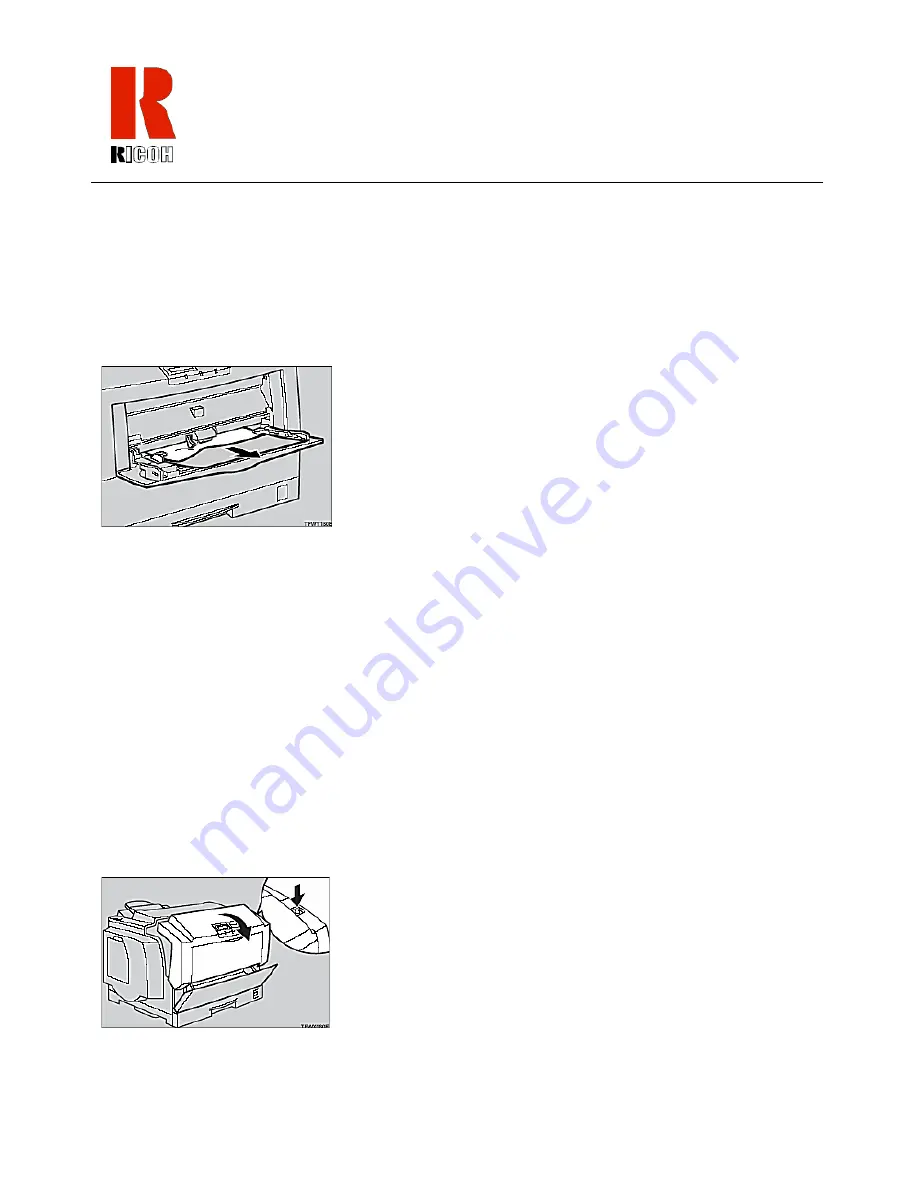
Follow the instructions below to remove the misfed paper from the bypass tray:
1

Carefully pull out the misfed paper making sure that you do not leave any misfed 
paper in the printer.

2

When paper is left in the bypass tray, remove the paper.

3

Close the bypass tray, open the front cover, and then close it to reset the misfeed 
condition.

4

Reload paper into the bypass tray.

Removing Misfed Paper from the Front Cover

Follow the instructions below when removing misfed paper from the front cover:

Warning:

When removing misfed paper, do not touch the fusing section. It 
is very hot and could cause a burn.

1

If the message OPEN FRONT COVER AND REMOVE MISFEED appears on 
the display panel, open the front cover by pushing the front cover release button.

Содержание AP505

Страница 1: ...OH COLOR LASER PRINTER AP505 OPERATING INSTRUCTIONS Read this manual carefully before you use this product and keep it handy for future reference For safety please follow the instructions in this manu...

Страница 2: ...Ricoh Corporation Address 5 Dedrick Place West Caldwell NJ 07006 Telephone number 973 882 2000 This device complies with part 15 of FCC Rules Operation is subject to the following two conditions This...

Страница 3: ...4 Installing the Paper Feed Unit Type305 16 Chapter 3 Loading Paper Reviewing the Paper Loading Options 21 Loading Paper in the Paper Tray 21 Specifying Paper Size Using the Operation Panel 23 Loading...

Страница 4: ...iv...

Страница 5: ...in a handy place near the machine Reviewing Exterior Front View Components This section describes the external front view components of the laser printer The following diagram illustrates the printer...

Страница 6: ...ront cover 7 Front cover Open this cover when accessing the inside of the printer 8 Left cover Open this cover when replacing the toner cartridge 9 Inset grips Hold the printer at the location indicat...

Страница 7: ...er printer The following diagram illustrates the position of these components Exterior rear view of laser printer The following table lists each component and its purpose This component Does this 1 Pa...

Страница 8: ...nector Note Rating voltage of the parallel interface connector for the computer is Max DC 5V 6 Network interface connector for 10BASE T 100BASE TX Plug the network interface cable for 10BASE T 100BASE...

Страница 9: ...ter Interior view of the laser printer The following table list each component and its purpose 8 Ventilator This hole allows air to circulate preventing components inside the printer form overheating...

Страница 10: ...receptacle for waste toner generated during the printing process 6 Photoconductor unit This contains a photoconductor unit that is used to compose the image being printed Note Screws are used to hold...

Страница 11: ...ists each component and its purpose This component Does this 1 Panel display The display shows the current status of the printer and error messages 2 On Line indicator The on line indicator tells you...

Страница 12: ...isplay 8 Power indicator The Power indicator stays on while the printer power is on The indicator stays off when the power is turned off or while the printer is in the Energy Save mode The indicator b...

Страница 13: ...socket and the printer 2 Set the printer s power switch to the On position The printer will take about eight minutes to warm up before it can print Power switch in the ON position Note When the print...

Страница 14: ...inter while it is blinking When the Error indicator lights up a printer error has occurred Use the message that appears on the operation panel to troubleshoot the problem 2 Set the printer s power swi...

Страница 15: ...ual The diagram below illustrates the three options that are available for this printer Available options for this printer You have the option of installing the 1 memory unit Type505 with either a 32M...

Страница 16: ...switch and remove all cables and cords from the printer 2 Remove the screws and remove the back plate as shown in the diagram below Note A coin can be used to remove the screws Caution The memory uni...

Страница 17: ...t Note There are two notches on the side with the connector of the memory unit They are located on the left and in the center Be sure to align the notches over the guides correctly as shown in the ill...

Страница 18: ...e Installing the Printer Hard Disk Type505 Follow the instructions below to install the printer hard disk type505 Warning Make sure you turn off the printer and wait for about 30 minutes before instal...

Страница 19: ...sk line up with the screw holes on the printer Fasten the hard disk with the screws that are enclosed using a screw driver 6 Attach the back plate to its original position Fasten it with the screws th...

Страница 20: ...rinter is equipped with the optional tray do not pull out more than one tray with paper at a time If you do the printer might tilt forward and cause damage to the equipment 1 Check the contents of the...

Страница 21: ...make an installation space Caution Be careful when lifting the printer as the right front side of the printer is significantly heavier than the left front side 4 Remove the paper feed unit from the bo...

Страница 22: ...er tray and remove the padding 7 Remove the ring attached to the red tag 8 If installing two paper feed units place one paper feed unit on the 4 upright pins of the other paper feed unit If installing...

Страница 23: ...e removed in step 2 12 Plug the printer s power cord back into the printer and the wall socket Turn on the power switch Note If the paper feed unit doesn t work follow the above instructions to reinst...

Страница 24: ...20 Operating Instructions...

Страница 25: ...r in the Paper Tray Follow the instructions below to load the paper in the paper tray 1 Carefully pull the paper tray out of the printer and place it on a flat surface 2 Slide the paper guides to posi...

Страница 26: ...the back paper guide and that the stack of paper is no higher than the limit mark inside the tray Caution After you load the paper you must set the paper size dial to match the actual paper size load...

Страница 27: ...the and arrow keys to display PRINTER SETUP 3 Press ENTER until SET SIZE appears 4 Use the and arrow keys to select YES and then press ENTER to display TRAY SIZE The currently selected paper size in t...

Страница 28: ...ng Paper in the Bypass Tray Follow the instructions below to load paper in the bypass tray Note Do not open the front cover when loading paper into the bypass tray 1 Open the bypass tray 2 Slide the s...

Страница 29: ...ender 4 Load paper until it stops with the print side down Caution Make sure the paper fits under the side guides The side guides should be set to the correct paper size to avoid paper feed problems D...

Страница 30: ...Use the and arrow keys to display PRINTER SETUP 3 Press ENTER until the BYPASS TRAY SIZE appears 4 Use the and arrow keys to select the paper size you have specified for the paper tray and then press...

Страница 31: ...the wall socket and the printer s power socket Turn on the printer s power switch See Turning the Printer On and Off on page 9 Is the interface cable properly connecting the printer to your com puter...

Страница 32: ...g increase the value of the I O timeout setting If the Data In indicator is blinking follow these steps to correct the situation Wait until the printer finishes receiving data from the computer Cancel...

Страница 33: ...ch any sections other than those specified in this manual If you do it will result in a burn 1 If the message REMOVE MISFEED FROM THE INPUT TRAY appears on the display panel pull out the paper tray ge...

Страница 34: ...per 3 Close the bypass tray open the front cover and then close it to reset the misfeed condition 4 Reload paper into the bypass tray Removing Misfed Paper from the Front Cover Follow the instructions...

Страница 35: ...because it is very hot and could cause a burn 3 When the misfed paper is in the main section of the photoconductor unit turn the dial downward then remove the misfed paper in the printer Make sure you...

Страница 36: ...D PAPER FROM THE OUTPUT TRAY appears open the paper exit cover 2 Open the front cover by pushing the front cover release button 3 Turn the dial downward then remove the misfed paper in the printer Not...

Страница 37: ...touch the fusing section It is very hot and could cause a burn 5 When you cannot see the misfed paper inside the printer remove the misfed paper from the output tray while turning the dial as shown in...

Страница 38: ...open flame If instructions are not followed it could result in serious injury or death Note Dispose of the toner cartridge at an authorized dealer or appropriate collection site If you dispose of the...

Страница 39: ...de it out until you can see the green tape 5 With your hand under the green tape remove the toner cartridge carefully as shown in the diagram below 6 Remove the protective sheet from the new toner car...

Страница 40: ...haken enough toner might not be evenly distributed in the cartridge In this case the print quality might be reduced 8 Slide the new toner cartridge into the printer 9 Return the lock lever to its orig...

Страница 41: ...starts warming up It takes a few minutes Replacing a Specific Toner Cartridge This procedure describes how to replace the magenta toner cartridge Use the same procedure to replace all other toner col...

Страница 42: ...t YES and then press ENTER The following message appears on the panel display MAGENTA TONER PLEASE WAIT The machine prepares itself for a new toner cartridge 6 Prepare the new toner cartridge for inst...

Страница 43: ...1 left 2 paper exit 3 D Data in indicator 8 Dial paper size 22 Display panel 7 E Enter key 8 Error indicator 8 Extender output tray 2 F Filter ozone 3 6 Front cover 2 30 Front cover release button 2...

Страница 44: ...pe505 11 paper feed unit type505 11 printer hard disk type505 11 Output tray 2 32 Ozone filter 3 P Panel display 7 Paper loading in bypass tray 24 specifying size for bypass tray 26 specifying size fo...

Отзывы: