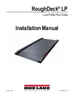
RoughDeck LP
4
Visit our website
2.0
Installation
There are threaded corner holes (1/2-20 NF) in the deck for removable eye bolts to allow lifting the deck from above with
chains. Because of the possibility of damage from forklift tines, the scale should always be lifted from above with chains through
the eye bolts.
Standard installation of the RoughDeck LP floor scale consists of the following steps:
1. Site Preparation (
2. Unpacking (
3. Floor installation (
)
4. Connecting Indicator Interface Cable (
)
NOTE: After installation is completed, corner correction (
) and calibration (
)
should be completed.
2.1 Site Preparation
Use the following guidelines for site preparation:
• The scale must not be loaded beyond its capacity, even momentarily. Do not select a site where overweight loads would
have to maneuver to avoid crossing the platform.
• Avoid areas where the scale might receive damaging side impacts from wheels or forklift tines, or shock damage from
falling objects.
• The interface cable between the scale and the indicator must be protected against crushing, cutting or moisture damage.
If necessary, run the cable through conduit or other protection to prevent damage.
For proper operation, the scale must be level within a 1/4 in (6.35 mm). Choose a site where the floor is close to this standard to
avoid excessive shimming, or modify the floor at the chosen site to meet this standard.
2.2 Unpacking
Remove all packing material and inspect scale for visible damage caused during shipment. Report any damage to the shipping
company and Rice Lake Weighing Systems immediately.
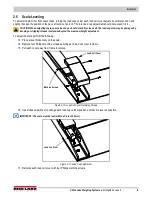
The RoughDeck LP has threaded holes in the deck to allow installation of eye bolts with shoulders for use when lifting the scale
with chains or using a spreader bar.
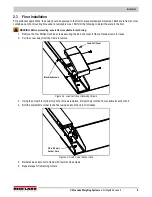
IMPORTANT: Lift the scale only with a properly designed spreader bar as shown in
. Lifting force must be vertical
to avoid bending the eye bolts.
WARNING: Lifting should always occur with the top plate facing up and the eye bolts securely attached through the nuts
welded to the bottom side of the top plate. In addition, shoulder support screws must be installed securely in each corner
(under load cell corner covers) to ensure lower frame is attached to the deck.
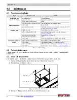
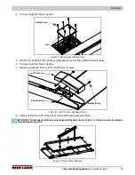
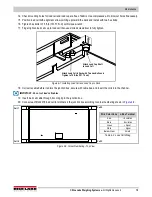
Figure 2-1. Proper Lifting Technique and Shoulder Support Screw Location
Use two 1/2 in eye bolts, insert into threaded holes
in opposite corners of top plate for lifting
Shoulder Screw Under Each Load Cell Cover
Содержание RoughDeck LP
Страница 1: ...RoughDeck LP Low Profile Floor Scale Installation Manual PN 212616 Rev A April 29 2022...
Страница 24: ...RoughDeck LP 20 Visit our website www RiceLake com...
Страница 25: ......

