LaserLight3 ConnexLink Wireless Radio Installation
6
Visit our website
Serial Configuration
After hardware installation, LaserLight3 software must be configured to communicate from its RS-232 port with the ConnexLink.
In order to function correctly, the Baud and Bits parameters in the LaserLight3 require setup.
NOTE: By default LaserLight3 is configured with the required parameters to operate the ConnexLink. Ensure that the
following settings are configured. If LaserLight3 default serial communication configuration has been altered, the system
will not function. For more information about LaserLight3, see LaserLight3 Large-Display Weight Indicator Technical
Manual (PN 213589) or LaserLight3 Remote Display Technical Manual (PN 214748).
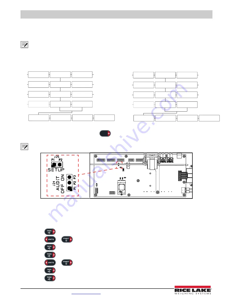
Figure 13. Baud/Bits Parameter Menu Path
1. Enable Setup mode by either pressing the
key (if a shunt is installed on J24 pins two and three) or opening
the LaserLight3 and shorting J25 pins momentarily.
NOTE: Enabling Setup mode grants access to various LaserLight3 menus that are restricted in normal operation, including
the Setup menu.
Figure 14. J24 Audit Jumper and J25 Setup Jumper
2. Perform one of the following:
• For LaserLight3 Remote Display, navigate to
Setup
▼
Comm ▼Serial ▼ RS232 1/2 ▼ Trigger ► Baud
• For LaserLight3 Large-Display Weight Indicator, navigate to
Audit
►
Setup
▼
Comm ▼Serial ▼ RS232 1/2 ▼
Trigger ► Baud
3. Press
. The configured Baud parameter setting displays.
4. Press
or
repeatedly until
9600
is selected.
5. Press
. The Bits parameter displays.
6. Press
. The configured Bits parameter setting displays.
7. Press
or
repeatedly until
8None
is selected.
8. Press
. The Stop Bits parameter displays.
9. Press
. The configured Stop Bits parameter setting displays.
RS232 1
RS32 2
20MA
Serial
USB
WiFi
Comm
Remote
Config
Trigger
Baud
Bits
Setup
Setpnt
Audit
Stop Bits
RS232 1
RS32 2
20MA
Serial
USB
WiFi
Comm
Remote
Format
Trigger
Baud
Bits
Setup
M
ac
ID
Version
Stop Bits
LaserLight3 Remote Display Serial Menu
LaserLight3 Large-Display Weight indicator Serial Menu
MENU


