


36
G
B
ELECTRIC LOCK
Horizontal lock - right external view - 12Vac
code ACG8660
Horizontal lock - left external view - 12Vac
code ACG8670
Vertical lock - 12Vac
code ACG8650
BATTERY
Battery 2,2Ah 12V
code ACG9515
BATTERY CHARGE CARD
code ACG4648
ACCESSORIES
For the connections and the technical data of the optional equipments follow the relevant handbooks.
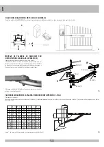
LONG LEVER
The long lever is suggested for a leaf with a distance up to 500 mm between the hinge
of the leaf and the internal side of the pillar.
code
ACG8034
STRONG BOX STONE
It is a strong metal (die-cast aluminium) container with lock to protect manual release and/or
push button. It is provided with a rocker switch and unlocking device (needs cable ACG8022). It
has to be embedded in the wall. In die-cast aluminium - IP54 code ACJ9078
STRONG BOX FLAT
It is a strong metal (die-cast aluminium) container with lock to protect manual release and/or
push button. It is provided with a rocker switch and unlocking device (needs cable ACG8022).
It has to be fitted onto the wall.
In die-cast aluminium - IP54
code ACJ9071
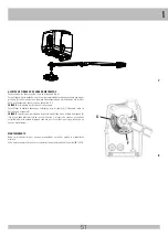
UNLOCKING CABLE
Cable for manual releasing the operators from outside, to be connected to strong box.
code ACG8022
FAULT
SOLUTION
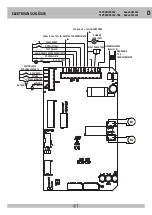
After having carried out the various connections and having supplied
voltage, all the LEDS are switched off.
Check fuses F1, FUSE 1.
If the fuse is blown, use only a suitable replacement.
F1 T 2A
TRANSFORMER PROTECTION FUSE (on the outside of the T2 PREMIER 24V board)
FUSE 1 8A MOTOR PROTECTION FUSE
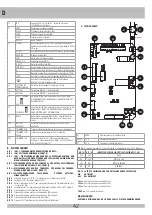
The motor opens and closes, but it has no strength and moves slowly.
Check trimmers RUN and LOW-SPEED adjustment.
The gate opens but does not close after the time set.
Make sure that the TCA trimmer is activated with LED DL6 on.
OPEN button always on, replace the OPEN control button or switch.
Sensor Auto test failed, check the connections between the control panel and the sensor power supply.
Warning:
If you are not using a power supply for the sensors, DIP 12 should be OFF.
The gate does not open or close by activating the various K, Radio, Open
and Close buttons.
Faulty safety edge contact. Faulty photocells contact with DIP 4 OFF.
Fix or replace the relative contact.
The electric lock does not work.
Ensure to have enabled DIP 8 at ON.
LED DL1 blinks rapidly and no movement is activated.
Place dip switches 1, 2 or 3 in the OFF position.


