background image

2

ISTRUZIONI DI SICUREZZA IMPORTANTI PER 

L’INSTALLAZIONE

I

ATTENZIONE - PER LA SICUREZZA DELLE PERSONE È IMPORTANTE CHE VENGANO 

SEGUITE TUTTE LE ISTRUZIONI

CONSERVARE CON CURA QUESTE ISTRUZIONI

1° -  Se non è previsto nel quadro elettronico, installare a monte del medesimo 

un’interruttore di tipo magnetotermico (onnipolare con apertura minima dei contatti 
pari a 3 mm) che riporti un marchio di conformità alle normative internazionali. 
Tale dispositivo deve essere protetto contro la richiusura accidentale (ad esempio 
installandolo entro quadro chiuso a chiave).

2° -  Per la sezione ed il tipo dei cavi la RIB consiglia di utilizzare un cavo di tipo H05RN-F 

con sezione minima di 1,5 mm2 e comunque di attenersi alla norma IEC 364 e alle 
norme di installazione vigenti nel proprio Paese.

3° -  Posizionamento di un’eventuale coppia di fotocellule: il raggio delle fotocellule deve 

essere ad un’altezza non superiore a 70 cm dal suolo e ad una distanza dal piano 
di movimento della porta non superiore a 20 cm. Il loro corretto funzionamento deve 
essere verificato a fine installazione in accordo al punto 7.2.1 della EN 12445.

4° -  Per il soddisfacimento dei limiti imposti dalla EN 12453, se la forza di picco supera 

il limite normativo di 400 N è necessario ricorrere alla rilevazione di presenza attiva 
sull’intera altezza della porta (fino a 2,5 m max). Le fotocellule in questo caso sono da 
applicare come indicato nella norma EN 12445 punto 7.3.2.2).

N.B.: È obbligatoria la messa a terra dell’impianto.

I dati descritti nel presente manuale sono puramente indicativi.
RIB si riserva di modificarli in qualsiasi momento.
Realizzare l’impianto in ottemperanza alle norme ed alle leggi vigenti.

ISTRUZIONI IMPORTANTI DI SICUREZZA PER L’INSTALLAZIONE

ATTENZIONE - L’INSTALLAZIONE NON CORRETTA PUÒ CAUSARE GRAVI DANNI

SEGUIRE TUTTE LE ISTRUZIONI DI INSTALLAZIONE

1° -  Questo libretto d’istruzioni è rivolto esclusivamente a del personale specializzato


che sia a conoscenza dei criteri costruttivi e dei dispositivi di protezione contro gli 
infortuni per i cancelli, le porte e i portoni motorizzati (attenersi alle norme e alle leggi 
vigenti).

2° -  L’installatore dovrà rilasciare all’utente finale un libretto di istruzioni in accordo alla 

12635.

3° -  L’installatore prima di procedere con l’installazione deve prevedere l’analisi dei 

rischi della chiusura automatizzata finale e la messa in sicurezza dei punti pericolosi 
identificati (seguendo le norme EN 12453 / EN 12445).

4° -  L’installatore prima di installare il motore di movimentazione deve verificare che il 

cancello sia in buone condizioni meccaniche e che si apra e chiuda adeguatamente.

5° -  

L’installatore dovrà installare l’organo per l’attuazione del rilascio manuale ad 
un’altezza inferiore a 1,8 m.

6° -  L’installatore dovrà rimuovere eventuali impedimenti al movimento motorizzato del 

cancello (es. chiavistelli, catenacci, serrature ecc.)

7° -  L’installatore dovrà applicare in modo permanente le etichette che mettono in guardia 

contro lo schiacciamento in un punto molto visibile o in prossimità di eventuali comandi 
fissi.

8° -  Il cablaggio dei vari componenti elettrici esterni all’operatore (ad esempio fotocellule, 

lampeggianti, ecc.) deve essere effettuato secondo la EN 60204-1 e le modifiche a 
questa apportate dal punto 5.2.2 della EN 12453. 

9° -  L’eventuale montaggio di una pulsantiera per il comando manuale del movimento 

deve essere fatto posizionando la pulsantiera in modo che chi la aziona non si trovi 
in posizione pericolosa; inoltre si dovrà fare in modo che sia ridotto il rischio di 
azionamento accidentale dei pulsanti.

10° 


Tenete i comandi dell’automatismo (pulsantiera, telecomando etc) 
fuori dalla portata dei bambini. L’organo di manovra (un interruttore tenuto 
chiuso manualmente) deve essere in una posizione che sia visibile dalla parte guidata 
ma lontana dalle parti in movimento. Deve essere installato a un’altezza minima di 
1,5 m.

11° -  Questo apparecchio può essere utilizzato da bambini di età compresa dagli 8 anni e 

al di sopra e le persone con ridotte capacità fisiche, sensoriali o mentali, o mancanza 
di esperienza e conoscenza se sono stati controllati o istruiti all’uso dell’apparecchio 
in modo sicuro e capire i rischi connessi.

12° -  I bambini non devono giocare con l’apparecchio.
13° -  Pulizia e manutenzione utente non deve essere fatta da bambini senza supervisione.
14° -  Non permettere ai bambini di giocare con i comandi fissi. Tenere i telecomandi lontano 

dai bambini.

15° -  I dispositivi di comando fissi devono essere installati in modo che siano visibili.
16° -  Prima di eseguire qualsiasi operazione di installazione, regolazione, manutenzione 

dell’impianto, togliere la tensione agendo sull’apposito interruttore magnetotermico 
collegato a monte dello stesso.

17° -  A fine installazione l’installatore dovrà assicurarsi che le parti della porta non 

ingombrino strade o marciapiedi pubblici.

LA DITTA RIB NON ACCETTA NESSUNA RESPONSABILITÀ per eventuali danni 
provocati dalla mancata osservanza nell’installazione delle norme di sicurezza e 
delle leggi attualmente in vigore.

IMPORTANT SAFETY INSTRUCTIONS FOR THE 

INSTALLATION 

G

B

ATTENTION - FOR THE SAFETY OF PEOPLE IT IS IMPORTANT TO FOLLOW ALL THE 

INSTRUCTIONS 

KEEP THESE INSTRUCTIONS WITH CARE 

1° -  If it is not forecast in the electric gearcase, install a switch of magneto thermic type 

upstream, (omni polar with minimum opening of the contacts of 3 mm) with a check of 
conformity to the international standards. Such device must be protected against the 
accidental lockup (for example by installing inside a locked board). 

2° -  For the section and the type of the cables RIB advices to use a cable of H05RN-F type 

with 1,5 sqmm minimum section and, however, to keep to the IEC 364 and installation 
standards in force in your country.  

3° -  Positioning of a possible couple of photoelectric cells: the radius of the photoelectric 

cells must be at a height of no more than 70 cm from the ground and at a distance not 
superior to 20 cm from the motion plane of the door. Their correct working must be 
verified at the end of the installation in accordance with the point 7.2.1 of the EN 12445

4° -  To fulfill the limits set by EN 12453, and in case the peak force exceeds the normative 

limit of 400 N it is necessary to have recourse to the active presence survey on the 
whole height of the door (up to max 2,5 m) - The photoelectric cells, in this case, must 
be applied in accordance with the point 7.3.2.2 of the EN 12445

N.B.: The earthing of the system is obligatory. 

The data described in this handbook are purely a guide. 
RIB reserves the right to change them in any moment. 
Carry out the system in the respect of the standards and laws in force.

IMPORTANT SAFETY INSTRUCTIONS FOR THE INSTALLATION 

ATTENTION - THE INCORRECT INSTALLATION CAN CAUSE SERIOUS DAMAGES 

FOLLOW ALL INSTALLATION INSTRUCTIONS

1° -  This handbook is exclusively addressed to the specialized personnel 

who knows 

the constructive criteria and the protection devices against accidents for motorized 
gates, doors and main doors (follow the standards and the laws in force).

2° -  The installer will have to issue a handbook to the final user in accordance with the 

12635. 

3° -  Before proceeding with the installation, the installer must forecast the risks analysis 

of the final automatized closing and the safety of the identified dangerous points 
(Following the standards EN 12453/EN 12445).

4° -   Before installing the motion motor, the installer must verify that the gate is in good 

mechanical conditions and that it adequately opens and closes. 

5° -  The installer must install the member for the manual release at a height inferior to 

1,8 m. 

6° -  The installer will have to remove possible impediments to the motorized motion of the 

gate (eg. door bolts, sliding bolts, door locks etc.)

7° -  The installer will permanently have to put the tags warning against the deflection on a 

very visible point or near possible fixed controls. 

8° -  The wiring harness of the different electric components external to the operator (for 

example photoelectric cells, flashlights etc.) must be carried out according to the EN 
60204-1 and the modifications to it done in the point 5.2.2 of the EN 12453. 

9° -  The possible assembly of a keyboard for the manual control of the movement must be 

done by positioning the keyboard so that the person operating it does not find himself 
in a dangerous position; moreover, the risk of accidental activation of the buttons must 
be reduced.  

10° -  Keep the automatism controls (push-button panel, remote control etc.) out of the 

children way. Command device for operating the motor (a switch manually closed) 
should be placed in area visible from the guided site and far from moving parts. It 
should be placed at least at 1,5 m height.

11° -  this appliance can be used by children aged from 8 years and above and persons with 

reduced physical, sensory or mental capabilities or lack of experience and knowledge 
if they have been given supervision or instruction concerning use of the appliance in 
a safe way and understand the hazards involved

12° -  children shall not play with the appliance
13° -  cleaning and user maintenance shall not be made by children without supervision
14° -  do not allow children to play with fixed controls. Keep remote controls away from 

children

15° -  Fixed command devices should be installed in a well visible way.
16° -  Before carrying out any installation, regulation or maintenance operation of the 

system, take off the voltage by operating on the special magneto thermic switch 
connected upstream.  

17° -  At the end of the installation, the installer will have to make sure that the parts of the 

door do not encumber streets or public sidewalks.

THE RIB COMPANY DOES NOT ACCEPT ANY RESPONSIBILITY for possible damages 
caused by the non observance during the installation of the safety standards and of 
the laws in force at present.

Содержание AA50600

Страница 1: ...vettato Patented EP 2 642 028 A1 DESTRA RIGHT SINISTRA LEFT Operatore Operator Alimentazione Power Supply Lunghezza max asta Max boom lenght Tempo di movimento Operating time Servizio Service Codice Code HIGHWAY DX 230V 50 60Hz 2 3 m min 1 s in apre min 1 5 s in chiude con rallentamenti attivati min 1 s in opening min 1 5 s in closing with active slow speed in approaching 100 AA50600 HIGHWAY SX AA...

Страница 2: ...a porta non ingombrino strade o marciapiedi pubblici LA DITTA RIB NON ACCETTA NESSUNA RESPONSABILITÀ per eventuali danni provocati dalla mancata osservanza nell installazione delle norme di sicurezza e delle leggi attualmente in vigore IMPORTANT SAFETY INSTRUCTIONS FOR THE INSTALLATION G B ATTENTION FOR THE SAFETY OF PEOPLE IT IS IMPORTANT TO FOLLOW ALL THE INSTRUCTIONS KEEP THESE INSTRUCTIONS WIT...

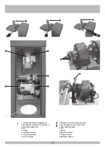
Страница 3: ...la bilanciamento asta 4 PLC 5 Inverter 6 Interruttore Generale 7 Sensori di prossimità 8 Fermi meccanici 1 Motorized system to re engage the boom 2 Fan cooled operator with service 100 3 Boom balancing spring 4 PLC 5 Inverter 6 Main Power Switch 7 Proximity sensors 8 Mechanical stoppers I G B ...

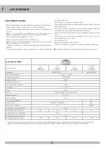
Страница 4: ...nza rimbalzo di ritorno e con asta in grado di assorbire l impatto per asta in carbonio Grado di protezione IP54 Manutenzione eseguibile ogni 2 000 000 di cicli Struttura in acciaio protetta con trattamento di cataforesi e verniciatura termoindurente N B È obbligatorio uniformare le caratteristiche dell impianto alle norme e leggi vigenti CARATTERISTICHE TECNICHE HIGHWAY DX Cod AA50600 SX Cod AA50...

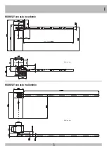
Страница 5: ...5 I HIGHWAY con asta in carbonio HIGHWAY con asta in alluminio Misure in mm Misure in mm ...

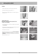
Страница 6: ... lo sportello aperto svitare le 3 viti che fissano il quadro elettronico quindi posizionatela a lato come da figura 4 Togliere il coperchio svitando i due dadi a farfalla posizionati all interno della colonna sotto il supporto motore nel vano del quadro elettronico Fig 5 6 Svitare e togliere il controdado Fig 7 Avvitare il dado con chiave a cricca da 22 come da TABELLA TARATURA MOLLE sottostante i...

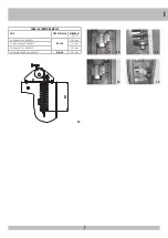
Страница 7: ...ARATURA MOLLE ASTA TIPO DI MOLLA MISURA M Fig 14 2 m Carbonio Cod ACG8620 ROSSA 323 mm 2 5 m Carbonio Cod ACG8621 307 mm 3 m Carbonio Cod ACG8622 293 mm 3 m Alluminio Ø 80 Cod ACG8501 GIALLA 307 mm I 11 12 10 13 14 ...

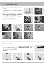
Страница 8: ...il connettore del sensore di sgancio asta Fig 23 Collegare il connettore del motore 2 di riarmo asta Fig 24 25 MONTAGGIO ASTA IN CARBONIO 15 16 26 19 27 21 29 23 25 18 20 28 22 30 24 17 MONTAGGIO MOZZO E ASTA Controllare che la superficie scoperta dell asta sia ben pulita e che all estremità sia presente il sistema di tenuta Fig 26 Inserire la parte scoperta dell asta nel mozzo porta asta Fig 27 p...

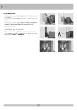
Страница 9: ...gio della molla Fig 40 41 come riportato nell apposita TABELLA TARATURA MOLLE 44 31 43 42 33 37 35 39 46 32 34 38 36 47 45 Prendere la linguetta ad incastro 8x7x20 ed inserirla nella sede dell albero porta mozzo Fig 44 45 Montare il mozzo sull albero in corrispondenza dello spacco con linguetta bloccandolo con 2 viti TCEI 10x70 inox 4 rondelle 10x20 inox e 2 dadi M10 autobloccanti Fig 46 47 ATTENZ...

Страница 10: ...el cavallotto Fig 55 facendo rimanere la parte del profilo dove vengono fissati gli accessori parallela e frontale al pavimento Fig 56 Serrare a fondo le viti Fig 57 Portare manualmente l asta in posizione orizzontale Rilasciare l asta verificando che si alzi fino al raggiungimento della completa apertura In caso l asta non si alzi verificare il corretto tiraggio della molla Fig 58 59 come riporta...

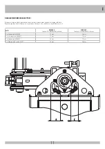
Страница 11: ...lato e fissato i finecorsa 3 e 4 posizionare i finecorsa 1 e 2 a contatto con i rispettivi finecorsa 3 e 4 ASTA MISURA A finecorsa 3 di rallentamento in apertura MISURA C finecorsa 4 di rallentamento in chiusura 2 m Carbonio cod ACG8620 32 mm 34 mm 2 5 m Carbonio cod ACG8621 37 mm 35 mm 3 m Carbonio cod ACG8622 42 mm 37 mm 3 m Alluminio Ø 80 cod ACG8501 49 mm 40 mm I ...

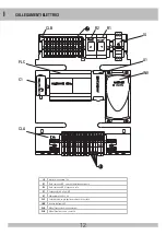
Страница 12: ...mando M2 di riaggancio asta C1 Condensatore 4 µF per M2 A1 Alimentatore 24Vdc 2 5A PLC Controllore logico per gestione comandi e sicurezze INV Inverter pilotaggio M1 CLA Morsettiera comandi e segnalazioni CLB Morsettiera finecorsa e sicurezze IG INV A1 PLC CLA C1 R1 R2 CLB COLLEGAMENTI ELETTRICI ...

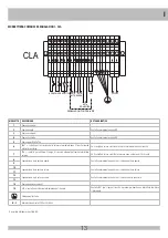
Страница 13: ...er abilitare il tempo di chiusura automatica tramite interruttore esterno Se il contatto è chiuso si abilita la chiusura dopo un tempo di 10 secondi 8 Segnalazione stato barriera aperta Contatto normalmente aperto che si chiude a barriera aperta 9 10 Segnalazione stato barriera chiusa Contatto normalmente aperto che si chiude a barriera chiusa 11 12 Segnalazione stato asta sganciata Contatto norma...

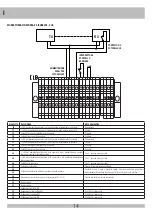
Страница 14: ...o nero 24 24V per alimentazione finecorsa asta sganciata o per alimentazione e contatto comune di eventuale fotocellula esterna Filo 2 sensore asta sganciata 25 24V per alimentazione finecorsa asta sganciata o per eventuale alimentazione fotocellula esterna Filo 3 sensore asta sganciata 26 Contatto asta sganciata Filo 1 sensore asta sganciata 27 Contatto nc fotocellula Tramite fotocellula esterna ...

Страница 15: ...er il passaggio di un nuovo veicolo si avrà una immediata inversione in apertura con successiva chiusura alla richiusura del contatto transito del veicolo completato È possibile escludere questa funzione aprendo il contatto dell interruttore o togliendo il ponticello a filo collegato ai morsetti 5 6 ECAT SGANCIO ASTA A BARRIERA CHIUSA Questa l operazione automatica di ripristino HIGHWAY apre a bas...

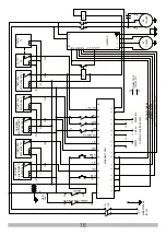
Страница 16: ... CHIUDE IB IC ID IE IF IG 14 15 5 6 7 0 0 0 0 0 0 0 0 1 2 3 4 5 6 7 8 B1 B2 B3 B4 B5 B6 B7 T1 T2 T3 T4 T5 T6 N F INVERTER 2 R 1 R M1 34 35 36 U V W µF 3 PHASE M2 1 PHASE 2 4 8 9 10 11 12 13 30 31 28 29 TCA MAN AUT 32 33 INTERRUTTORE SPORTELLO PHOTO NC LSSO LSO LSC LSSC LS SGANCIATA CONTROLLO POSIZIONE ASTA APERTA CHIUSA SGANCIATA CAT ECAT MAN AUT NON COLLEGATO SEGNALE CHIUDE SEGNALE VELOCITA ALTA ...

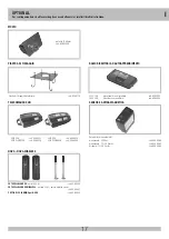
Страница 17: ...47 COPPIA DI COLONNINE per NOVA cod ACG8039 PIASTRA DI FISSAGGIO Piastra di fissaggio da interrare cod ACG8110 SUN 2CH cod ACG6052 SUN 4CH cod ACG6054 SUN CLONE 2CH cod ACG6056 SUN CLONE 4CH cod ACG6058 TELECOMANDO SUN MOZZO RADIO RICEVITORI AD AUTOAPPRENDIMENTO S433 1CH monocanale con morsettiera cod ACG5082 S433 2CH bicanale con morsettiera cod ACG5084 OPTIONAL Per i collegamenti ed i dati tecni...

Страница 18: ...rection without return rebound and with a boom that can absorb the impact for carbon boom IP54 degree of protection Average time from use without maintenance 15 000 hours Steel structure protected by cataphoresis treatment and thermoset coating N B It is obligatory to standardize the characteristics of the system to the rules and laws in force TECHNICAL CHARACTERISTICS HIGHWAY DX Cod AA50600 SX Co...

Страница 19: ...19 G B HIGHWAY with carbon boom HIGHWAY with aluminium boom Measurements in mm Measurements in mm ...

Страница 20: ...nscrew the 3 screws that secure the electronic panel then position it at the side as shown in figure 4 Remove the cover by loosening the two butterfly nuts positioned inside the column under the motor support in the compartment of the electronic panel Fig 5 6 Unscrew and remove the lock nut Fig 7 Tighten the nut with a 22 ratchet wrench as per the SPRING CALIBRATION TABLE below according to the bo...

Страница 21: ...NG CALIBRATION TABLE BOOM SPRING TYPE M Pict 14 2 m Carbon Code ACG8620 RED 323 mm 2 5 m Carbon Code ACG8621 307 mm 3 m Carbon Code ACG8622 293 mm 3 m Aluminum Ø 80 Code ACG8501 YELLOW 307 mm G B 11 12 10 13 14 ...

Страница 22: ... 22 Connect the boom uncoupling sensor connector Fig 23 Connect the connector of motor 2 of the boom reset Fig 24 25 CARBON ROD ASSEMBLY 15 16 26 19 27 21 29 23 25 18 20 28 22 30 24 17 HUB AND BOOM ASSEMBLY Check that the exposed surface of the boom auction is thoroughly cleaned and that the sealing system is present at the end Fig 26 Insert the exposed part of the boom into the boom holder hub Fi...

Страница 23: ... the spring Fig 40 41 as shown in the appropriate SPRING CALIBRATION TABLE 44 31 43 42 33 37 35 39 46 32 34 38 36 47 45 Take the 8x7x20 latch and insert it into the seat of the hub holder shaft Fig 44 45 Assemble the hub on the shaft in the correspondence with the latch locking it with 2 stainless steel 10x70 TCEI screws 4 stainless steel 10x20 washers and 2 M10 self locking nuts Fig 46 47 CAUTION...

Страница 24: ...the boom Ø80 into the jumper Fig 55 making the part of the profile remain where the accessories are fixed parallel and to front of the floor Fig 56 Tighten the screws to the floor Fig 57 Manually bring the boom to a horizontal position Release the boom checking that it rises until it reaches complete opening If the boom does not rise check the correct pulling in the spring Fig 58 59 as shown in th...

Страница 25: ...ing limit switches 3 and 4 position limit switches 1 and 2 in contact with the respective limit switches 3 and 4 BOOM MEASUREMENT A limit switch 3 to slow down during opening MEASUREMENT C limit switch 4 to slow down during closing 2 m Carbon code ACG8620 32 mm 34 mm 2 5 m Carbon code ACG8621 37 mm 35 mm 3 m Carbon code ACG8622 42 mm 37 mm 3 m Aluminium Ø80 code ACG8501 49 mm 40 mm G B ...

Страница 26: ...relay for boom release C1 Capacitor 4 µF for M2 A1 24Vdc Power Supply 2 5A PLC Logic controller for management and safety commands INV M1 Inverter drive CLA Controls and signals terminal board CLB Safety limit and safety terminal block IG INV A1 PLC CLA C1 R1 R2 CLB ELECTRICAL CONNECTIONS ...

Страница 27: ...sit 7 TCA contact to enable the automatic closing time via an external switch If the contact is closed it enables the lock after a time of 10 seconds 8 Report of open barrier state Contact normally open that closes with the barrier open 9 10 Report of closed barrier state Contact normally open that closes with the barrier closed 11 12 Report of release boom state Contact normally open that closes ...

Страница 28: ...k wire 23 Slowdown limit switch Contact in closing Black wire 24 24V for released boom limit switch power supply or for power supply and common contact of any external photocell Wire 2 Released boom sensor 25 24V for released boom limit switch power supply or for any external photocell power supply Wire 3 Released boom sensor 26 Released boom sensor Wire 1 Released boomsensor 27 Photocell NC conta...

Страница 29: ... for the passage of a new vehicle there will be an immediate reversal in opening with subsequent closing at the re closing of the contact transit of the completed vehicle It is possible to exclude this function by opening the contact of the switch or removing the wire jumper connected to terminals 5 6 ECAT BOOM UNCOUPLING WITH THE BARRIER CLOSED This is the automatic reset operation HIGHWAY opens ...

Страница 30: ...EN CLOSE IB IC ID IE IF IG 14 15 5 6 7 0 0 0 0 0 0 0 0 1 2 3 4 5 6 7 8 B1 B2 B3 B4 B5 B6 B7 T1 T2 T3 T4 T5 T6 N F INVERTER 2 R 1 R M1 34 35 36 U V W µF 3 PHASE M2 1 PHASE 2 4 8 9 10 11 12 13 30 31 28 29 TCA MAN AUT 32 33 SWITCH DOOR PHOTO NC LSSO LSO LSC LSSC LS DISLOCATED REPORT BOOM OPEN CLOSE DISLOCATED CAT ECAT MAN AUT NOT CONNECTED CLOSE SIGNAL FAST SPEED SIGNAL MAINTAINING TORQUE SIGNAL COMM...

Страница 31: ...IR OF COLUMNS for NOVA code ACG8039 BASE PLATE Base plate code ACG8110 SUN 2CH cod ACG6052 SUN 4CH cod ACG6054 SUN CLONE 2CH cod ACG6056 SUN CLONE 4CH cod ACG6058 RADIO TRANSMITTER SUN FIXING HUB CODE LEARNIG SYSTEM RADIORECEIVERS S433 1CH 1 channel with terminal block code ACG5082 S433 2CH 2 channels with terminal block code ACG5084 ACCESSORIES For the connections and the technical data of the op...

Страница 32: ...ntuali ispezioni da parte di organismi autorizzati This maintenance log contains the technical references and records of installation works maintenance repairs and modifications and must be made available for inspection purposes to authorised bodies NOME INDIRIZZO TELEFONO NAME ADDRESS TELEPHONE NUMBER Data Date Descrizione dell intervento installazione avviamento verifica delle sicurezze riparazi...

Страница 33: ...33 BA03240DX GRUPPO RICAMBIO HGW 2ML DX BA03240SX GRUPPO RICAMBIO HGW 2ML SX COMPONENTI DA SOSTITUIRE OGNI 2 000 000 DI CICLI COMPONENTS TO CHANGE EVERY 2 000 000 CYCLES ...

Страница 34: ...TTO AGGANCIO ASTA HGWY CME8224 TASSELLO ELASTICO FERMO ASTA H CME8230 BUSSOLA ANT SNODO HIGHWAY CSU211 SUPPORTO LAM STAMP KLM PFL 205 CTC1012 CHIAVETTA 20 7 8 CTC1214I SPINA CIL 8X32 INOX CTC1396 MOLLA AMMORTIZZATORE HIGHWAY CVA1711 SACCHETTO CM 15X40 25MY CVA2285 MOLLA GAS RAYFLEX 8X20X600 80N DDD10MA DADO AUTOB 10MA ALTO DDD8MAI DADO AUTOB 8MA INOX DIN 982 DDDB8MAI DADO AUTOB 8MA BASSO INOX 985 ...

Страница 35: ...142 CEL1721 ZOCCOLO VITE FD9472SMA CEL1722 C40A 1P N C 16A 4 5KA SNA9N1 CEL1723 RELE INNESTO2SC 24VCC 10A FD CEL1733 MICRO 3 POSIZ OMRON D2D2100 CEL1737 CONNETT 3POLI FEM 8 7 PHOENIX CEL1738 CONNETT 4POLI FEM 8 7 PHOENIX CEL1741 TAPPO PHX 8 7 NERO PA1410604 6 CME8210 ALBERO TRAINO SALDATO CME8211 DISTANZIALE LATO FINECORSA CME8212 CAMMA X MOLLA Z25 CME8213 TIRANTE MOLLA BILANCIAMENTO CME8214 DISTA...

Страница 36: ...U Directive 2006 42 EC have been applied to the product Compliance with the cited harmonized standards provides presumption of conformity with the specified essential requirements of the Directive covered by those Standards or parts thereof WARNING Other requirements and other EU Directives may be applicable to the products falling within the scope of this Declaration L oggetto della dichiarazione...

Отзывы: