15
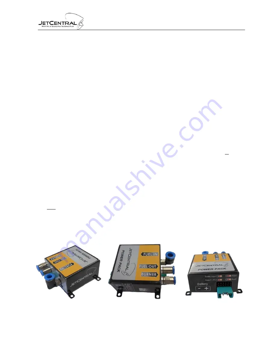
3.1 POWERPACK / ECU
Connections:
·
Throttle input to the receiver: JR type servo cable (Throttle RX)
·
Multiplex Battery input
·
S-BUS Multiplex connector
·
Hand Data Terminal / PC interface
·
6mm Fuel line inlet
·
4mm Fuel Line Outlet
·
3mm Burner Fuel Outlet
Note: In all power cables the black is the common and negative. This means that all the black
cables are connected internally together and to the negative of the pump/starter battery.
Connect the cables to their assigned places, Note that some of the JR type connectors used
can be connected in the wrong location or inverted.
Use the colored labels on the
POWERPACK / ECU
body to connect the connectors in to their
assigned place. The input / output connectors have been designed to prevent damage to the
internal circuitry in the case of an incorrect connection.
IMPORTANT!
Use only 5 cell 6V packs on your receiver; this will insure proper
operation of the POWERPACK / ECU electronics. You can use a regulator if wished
but we find 6V packs work just fine with today's radio equipment. Tests have shown
that turbine electronics may be affected from glitches by using lower 4.8 Volt packs
powering the radio system.
·
Use the recommended (supplied) starter motor battery type, the two supported
battery types are LiPo 2s or A123 3s.


