VALVE SERVICE
REPLACING SECTIONS
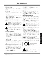
For clarification, the inlet cover [cover containing main
relief cartridge (18) ] will be called the left end of the valve
assembly.
Reassemble valve on a flat surface to insure proper
section alignment.
1. Remove handle assembly from section being
removed.
2. Remove valve from backhoe.
3. Thoroughly clean valve assembly.
4. Before disassembly, mark each section numerically to
avoid incorrect reassemble.
5. Remove four hex nuts and lock washers from right
(outlet cover) end of valve.
6. Slide outlet cover and each section off tie rods.
7. Replace sections as needed. Reassemble valve.
NOTE: Refer to Replacing Section Seals if seals need to
be replaced.
WARNING: Do not prelube O-ring section
seals prior to installation. Compression of
lubricants can distort valve causing spool
binding.
8. Torque stud nuts evenly to 15ft. Lbs .
CAUTION: If stud nuts are not tightened to
proper torque, valve spools may bind or stick,
or cause O-ring seals to extrude.
9. Reinstall handle assembly. Use locite 242 (blue) on all
screws.
REPLACING SECTION SEALS
1. Disassemble valve as described in previous section.
2. Remove old O-ring section seals. Be careful not to
scratch or otherwise damage sealing surface areas.
3. Thoroughly clean O-ring counter bores and surfaces of
each valve section.
4. Place valve assembly on a flat surface for reassembly.
5. Replace four O-ring seals. Seal Kit contains the
number of section seals required for one work
section/inlet cover.
6. Replace work sections on assembly studs in reverse
order in which they were removed. O-ring counter
bores (with O-rings in place) should be to your right
(downstream side of section) with inlet cover on your
left.
NOTE: Use care when sliding work sections on tie rods
to avoid dislodging O-rings.
7. When all work sections and outlet cover are positioned
on the assembly studs, replace lock washers and nuts.
8. Support alve on valve mounting brackets (Item 24,
p.22). Tap all sections downward with rubber mallot to
align sections evenly against rods.
8. Torque stud nuts evenly 15ft. Lbs.
SPOOL SEAL REMOVAL
1. Remove handle assembly. Center two sections -
Remove clevis pin from spool.
2. Remove bonnet and spool positioner assembly from
rear of the work section.
3. Carefully slide spool out of valve housing.
4. Remove old spool seals. Be careful not to scratch or
damage spool bore and sealing surfaces.
5. Thoroughly clean both seal grooves and exposed end
of spool.
SPOOL SEAL INSTALLATION
1. Lightly oil and insert one new spool seal in handle end
(front) seal groove of valve housing. Verify seal fit by
carefully running your finger around exposed edge of
seal. Seal should have a perfect ridge with no kinks or
twists.
2. Lightly oil valve spool and, starting from positioner end
(rear), reintroduce spool into valve housing.
3. Slowly push spool past seal with a twisting motion.
Stop when seal groove is exposed on positioner end.
CAUTION: Do not pull spool too far, as this
will allow seal in front groove to enter a spool
groove. Seal may be cut when spool is
pushed back.
4. Lightly oil and insert remaining spool seal in bonnet
end seal groove. Verify seal fit by carefully running your
finger around exposed edge of seal. Seal should have
a perfect ridge with no kinks or twists.
5. Return spool to center position with a twisting motion.
6. Reattach spool positioner. Use loctite 242 (blue) thread
locking compound on spool screw holding positioner
parts to spool. Be careful not to over torque this screw
and twist it off. Use 7ft. lb. maximum torque. Slide
bonnet in place. Replace bonnet screws. Torque
bonnet screws to 5-7 ft. Lbs.
7. Replace spool clevis pin and handle assembly.
REPLACING DAMAGED BACKUP RINGS
Backup rings are installed at the factory using a special
sizing tool.
Do not replace backup rings offered in seal kits unless
original ring has been damaged.
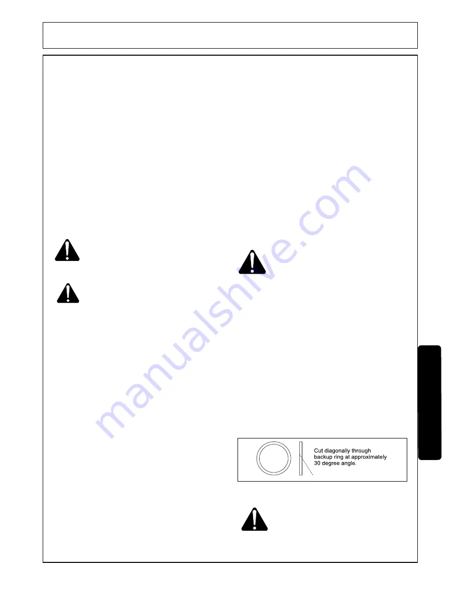
1. If backup ring must be replaced, cut replacement
backup ring as shown.
CAUTION: Make only one diagonal cut in
backup ring. Do not cut backup ring into two
pieces.
2. Slip backup ring over cartridge and into place.
MAINTENANCE
MAINTENANCE
F3788-7-04
Maintenance Section 5-7
© 2004
Alamo Group Inc.
Содержание 95HD
Страница 4: ...Safety Section 1 1 SAFETY SECTION 2004 Alamo Group Inc...
Страница 11: ...F3788 7 04 Safety Section 1 8 SAFETY SAFETY 2004 Alamo Group Inc...
Страница 16: ...INTRODUCTION SECTION Introduction Section 2 1 2004 Alamo Group Inc...
Страница 19: ...F3788 7 04 Introduction Section 2 4 SPECIFICATIONS INTRODUCTION INTRODUCT ION 2004 Alamo Group Inc...
Страница 20: ...Assembly Section 3 1 ASSEMBLY SECTION 2004 Alamo Group Inc...
Страница 24: ...Operation Section 4 1 OPERATION SECTION 2004 Alamo Group Inc...
Страница 29: ...MAINTENANCE SECTION Maintenance Section 5 1 2004 Alamo Group Inc...
Страница 37: ...MAINTENANCE MAINTENANCE F3788 7 04 Maintenance Section 5 9 2004 Alamo Group Inc...
Страница 42: ...95HD SOM 7 04 Printed U S A P N F 3788...


