background image

20

Post Start-Up Inspection

Feel the inlet and outlet pipes. Outlet pipe should be
only slightly warmer than the inlet. It should not be hot.

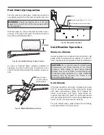
With the heater on, remove the door and make a visu-
al check of the pilot and burner. The flame should be
blue with a well-defined pattern.

A  yellow  or  "floating"  flame  indicates  restricted  air
openings  or  incorrect  orifice  size.  Should  this  occur,
shut the heater off and contact the installer or gas sup-
plier.

WARNING:

Should  overheating  occur  or  the  gas

supply fail to shut off, turn off the manual gas control
to the appliance.

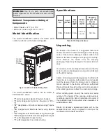
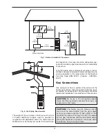
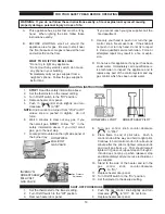
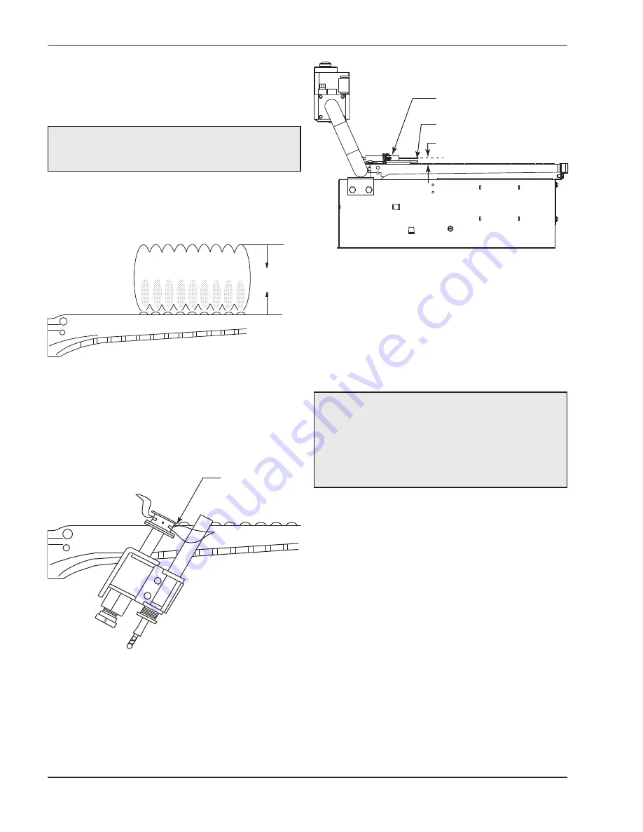
4“ MAX

Fig. 22: Correct Main Burner Flame Pattern

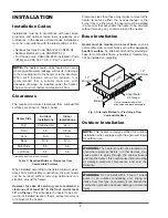
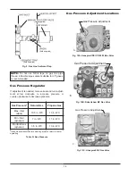
Head of Pilot
must be above
Burner Deck.

Fig. 23: Millivolt Pilot Burner Flame

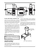
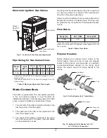
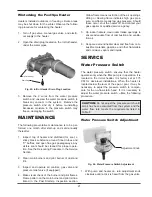
Igniter 

Minimum Spark Gap is 0.15” - 0.18” 

3/8” Nominally from burner surface

Fig. 24: DSI Igniter Location

Cold Weather Operation

Moderate Climate

Heater operation can continue during short-term cold
spells. When temperatures are between 0° and 32°F,
flow (continuous pump operation) must be maintained.

Cold Climate

Prolonged  operation  with  water  temperatures  below
50°F  is  not  recommended.  When  starting  the  heater
with  water  temperatures  below  50°F,  operate  the
heater  continuously  until  higher  temperatures  are
reached.  Operating  the  heater  for  prolonged  periods
with pool water below 50°F can seriously damage the
heater, and is not covered by the warranty.

For  cold  climate  areas,  please  follow  the  winterizing
procedures listed in the next section.

CAUTION:

Do not use the heater to maintain water

temperatures  just  above  freezing  or  for  freeze
protection.  When  heater  is  used  during  freezing
weather,  care  must  be  taken  to  avoid  freeze-ups.
Continuous  pump  operation  is  a  must.  Additional
protection  may  be  required.  The  heater  is  not
warranted against freeze-ups.

Содержание Versa Heaters

Страница 1: ...To do so may result in an explosion or fire WHAT TO DO IF YOU SMELL GAS Do not try to light any appliance Do not touch any electrical switch do not use any phone in your building Immediately call your...

Страница 2: ...2 Rev 10 reflects the following Changes to Warnings on page 4 Model Identification on page 7...

Страница 3: ...ring Diagrams 17 Post Start Up Inspection 20 Cold Weather Operation 20 MAINTENANCE 21 SERVICE 21 Water Pressure Switch 21 Flame Roll Out Safety Switch 22 High Limits 22 Pilot Safety Millivolt Models 2...

Страница 4: ...d service must be performed by a qualified installer service agency or the gas supplier WARNING To minimize the possibility of improper operation serious personal injury fire or damage to the heater A...

Страница 5: ...your water Automatic Chlorinators Chemical Feeders All chemicals must be introduced and completely dilut ed into the pool or spa water before being circulated through the heater Do not place sanitizin...

Страница 6: ...verages before or during spa or hot tub use may cause drowsiness which could lead to unconsciousness and subsequently result in drowning 3 Pregnant Women Beware Soaking in water over 102 F 39 C may ca...

Страница 7: ...f the carton is damaged make a note to that effect on the Bill of Lading when signing for the ship ment Remove the heater from the shipping packaging Report any damage to the carrier immedi ately On o...

Страница 8: ...open Fig 3 Alternate Method for Providing a Non Combustible Base Clearances less than these may require removal of the heater to service either the heat exchanger or the burner tray In either case the...

Страница 9: ...elow or to either side of any opening into the building Refer to the latest revisions of CAN CSA B149 Outdoor High Wind Top High Wind Conditions Outdoor Units Only In areas where high winds are freque...

Страница 10: ...the same size as the drafthood outlet is recommended however when the total vent height is at least 10 ft drafthood relief opening to vent terminal the vent pipe size may be reduced as specified in th...

Страница 11: ...be used as specified in the latest edition of the National Flue Gas Code ANSI Z223 1 Canada CAN CSA B149 Gas Connections Gas piping must have a sediment trap ahead of the heater gas controls and a ma...

Страница 12: ...ure or counter clockwise to decrease pressure Gas Pressure Natural Gas Propane Gas Max Inlet static 10 5 in WC 13 in WC Min Inlet dynamic 7 in WC 11 in WC Manifold Gas dynamic 3 5 in WC 10 in WC Stati...

Страница 13: ...3 1 53 Specific Gravity 0 5 in WC Pressure Drop Table E Maximum Equivalent Pipe Length Plumbing from the heater back to the pool or spa must not have any valves or restriction that could prevent flow...

Страница 14: ...ow 50 F It also serves to eliminate needless pressure drop through the heater and accompanying reduction in the flow rate to the spa jets etc Bypass Disc Spring Bypass Body Fig 14 Internal Automatic B...

Страница 15: ...130A Pressure Drop When installing a remote switch do not exceed 10 ft of wiring from the heater Use 18 gauge stranded wire Electronic Heaters The Direct Spark Ignition Device automatically lights the...

Страница 16: ...EN WHITE SUPPLY SIDE Fig 18 240V Hook Up Control Adjustments Millivolt The pool or spa water temperature is controlled by the thermostat on the upper front panel of the heater The control center conta...

Страница 17: ...ostat Manual Switch Switch Switch AGS Water Press Gas Valve Roll Out Valve Pilot Generator To Firemans Switch field installed Optional BK BK R Y BK TH PP W R PP TH V BK V BK O O Fig 20 Wiring Diagram...

Страница 18: ...ontrol which has been under water 1 STOP Read the safety information above 2 Set the thermostat to the lowest setting 3 Turn off all electrical power to the appliance 4 This appliance is equipped with...

Страница 19: ...d from Pilot to Off unless knob is pushed in slightly Do not force 6 Wait 5 minutes to clear out any gas If you then smell gas STOP Follow B in the safety information above If you don t smell gas go t...

Страница 20: ...SI Igniter Location Cold Weather Operation Moderate Climate Heater operation can continue during short term cold spells When temperatures are between 0 and 32 F flow continuous pump operation must be...

Страница 21: ...trated in the Post Start Up Inspection section In Out Header Drain Plug Fig 25 In Out Header Drain Plug Location Yellow flame means restriction of the air openings Lifting or blowing flame indicates h...

Страница 22: ...re switch See Illustrated Parts List for 11 psi water pressure switch CAUTION Do not operate the heater without the function of a properly adjusted water pressure switch or flow switch Fig 27 Flame Ro...

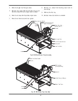
Страница 23: ...9 Slide out burner tray 10 Reverse above procedure to reinstall Rear Hold Down Bracket Burner Millivolt Pilot Assembly under Pilot Shield Millivolt Gas Valve Invensys shown Manifold Pilot Lighter Tube...

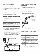
Страница 24: ...burner hold down bracket and spacer can become distorted from direct flame impingement and this usually necessitates replacement of these parts ORIFICES MUST BE PARALLEL WITH BASE TOLERANCE OF 2 0 IGN...

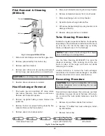
Страница 25: ...nstall Tube Cleaning Procedure Establish a regular inspection schedule the frequency depending on the local water conditions and the sever ity of service Do not let the tubes clog up solidly Clean out...

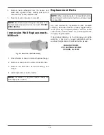
Страница 26: ...DO NOT WIRE BRUSH Fig 35 Immersion Well Assembly Replacement Parts Any part returned for replacement under standard company warranties must be properly tagged with a return parts tag completely filled...

Страница 27: ...burners Outer jacket very hot Broken refractory caused by paint blistered shipping damage or improper combustion Replace refractory panels Excessive sooting of heat exchanger Determine cause of sooti...

Страница 28: ...jumper Replace thermostat Replace high limit that prevented from firing Jump across both TH wires on gas valves Check gas supply gas line size gas pressure Also check for insects or debris in pilot a...

Страница 29: ...ive Red Positive 2 Pilot Load 500mV 100 Pilot generator connected to valve Power applied to pilot solenoid TP Thermopile Robertshaw PP Power Pile Honeywell TH TP Common Invensys TH PP Common Honeywell...

Страница 30: ...tension wire is properly connected to the igniter Check the gas valve There must be 24VAC while the ignition module is sparking Check the igniter Igniter may not be sensing correctly Check that the s...

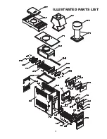
Страница 31: ...31 ILLUSTRATED PARTS LIST...

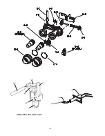
Страница 32: ...32 5 P 1 P 3 P 4 P 2 P 6 P HONEYWELL MILLIVOLT PILOT 7 P 8 P...

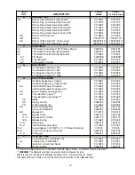
Страница 33: ...ange Assy Cupro Nickel 011593F 011593F 2 H Inlet Outlet Header Complete 011594F 011594F Inlet Outlet Header Includes 6 H 011595F 011595F 3 H Return Header Includes 6 H 011596F 011596F 4 H Tube Bundle...

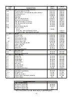
Страница 34: ...Pilot Generator MV 600019B 600019B 4 P Pilot Mounting Bracket MV 011610F 011610F 5 P Lighter Tube MV 052797 052797 6 P Pilot Tube MV 004078F 004078F 7 P Ignitor DSI 011611F 011611F 8 P Hi Tension Wire...

Страница 35: ...35...

Страница 36: ...www raypak com Raypak Inc 2151 Eastman Avenue Oxnard CA 93030 805 278 5300 Fax 805 278 5468 Litho in U S A...

Отзывы: