Rheem RA17 Series Скачать руководство пользователя страница 49

49

DIAGNOSTICS

Service Analyzer Charts

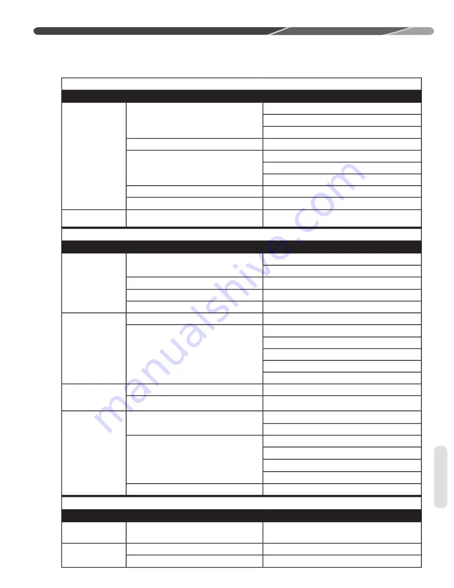
COMPRESSOR OVERHEATING (cont.)

SYMPTOM

POSSIBLE CAUSE

CHECK OR REMEDIES

Short cycling of  

compressor (cont.)

Distributor tube

Restricted with foreign matter

Kinked

I.D. reduced from previous compressor failure

Low charge

Check system charge.

ow evaporator air ow

Dirty coil

Dirty  lter

Duct too small or restricted

Faulty run capacitor

Replace.

Faulty internal overload

Replace compressor.

Faulty Compressor 

Valves

ast equali ation ow pressure di erence

Replace compressor and examine system to 

locate reason.

ELECTRICAL

SYMPTOM

POSSIBLE CAUSE

CHECK OR REMEDIES

Voltage present on 

load side of com-

pressor contactor 

and compressor 

won't run

Compressor start components

Check start capacitor.

Check potential relay.

Run capacitor

Check with ohmmeter

Internal overload

Allow time to reset.

Compressor windings

Check for correct ohms.

Voltage present on 

line side of com- 

pressor contactor 

only

Thermostat

Check for control voltage to contactor coil.

Compressor control circuit

High-pressure switch

Low-pressure switch

Ambient thermostat

Solid-state protection control or internal thermal sensors

ompressor timed o on control or interloc

No voltage on line 

side of compressor 

contactor

Blown fuses or tripped circuit breaker

Check for short in wiring or unit.

Improper wiring

Recheck wiring diagram.

Improper voltage

High voltage

Wrong unit

Power supply problem

Low voltage

Wrong unit

Power supply problem

Wiring undersized

Loose connections

Single Phasing (3 phase)

Check incoming power and fusing.

FLOODED STARTS

SYMPTOM

POSSIBLE CAUSE

CHECK OR REMEDIES

Liquid in the com-

pressor shell

Faulty or missing crankcase heater

Replace crankcase heater.

Too much liquid in 

system

Incorrect piping

Check piping guidelines.

Overcharge

Check and adjust charge.

Diagnostics

Содержание RA17 Series

Страница 1: ...ER INSTALLATION ADJUSTMENT AND OPERATION OF THIS UNIT READ THESE INSTRUCTIONS THOROUGHLY BEFORE ATTEMPTING INSTALLATION OR OPERATION FAILURE TO FOLLOW THESE INSTRUCTIONS MAY RESULT IN IMPROPER INSTALL...

Страница 2: ...perature Sensor 22 UP and SELECT Buttons 22 Memory Card 22 EcoNet Communication System Control Wiring 22 EcoNet Communication System ICC Control 22 Condensing Units 23 Active Compressor Protection Mod...

Страница 3: ...f the heat pump and may also endanger life and property The manufacturer disclaims any responsibility for such loss or injury resulting from the use of such unauthorized components accessories or devi...

Страница 4: ...or concealed should be filed immediately with the shipping company Check model number electrical characteristics and accessories to determine if they are correct Check system components indoor coil ou...

Страница 5: ...20 25 25 40 40 50 50 19 76 1 84 22 23 2 07 32 30 3 00 32 30 3 00 1 1 1 1 5133 2423 3540 1671 4251 2006 5133 2423 128 3629 151 4281 204 5783 223 6322 160 72 6 180 81 6 231 104 8 241 109 3 167 75 7 187...

Страница 6: ...ant charge and proper airflow are critical to achieve rated capacity and efficiency Installation of this product should follow the manufacturer s refrigerant charging and airflow instructions Failure...

Страница 7: ...ss 60 152 4 cm above fan discharge unit top to prevent recirculation 6 15 2 cm to coil grille air inlets with 12 30 5 cm minimum recommended Corrosive Environment The metal parts of this unit may be s...

Страница 8: ...ering the unit Unit Mounting WARNING Secure an elevated unit and its elevating stand in order to prevent tipping Failure to do so may result in severe personal injury or death If installing a unit on...

Страница 9: ...410A and air should never be mixed in tanks or supply lines or be allowed to accumulate in storage tanks Leak checking should never be done with a mixture of R 410A and air Leak checking can be perfor...

Страница 10: ...vaporator specifically designed for R 410A Location Do not install the indoor coil in the return duct system of a gas or oil furnace Provide a service inlet to the coil for inspection and cleaning Kee...

Страница 11: ...nit It is important not to allow the refrigerant to ash any superheated vapor prior to the expansion device of the indoor coil The ashing of refrigerant can occur for the following reasons ow refriger...

Страница 12: ...rence the long line set section of the I O for detail Long Line Set Applications ong line set applications are de ned as ap plications that require accessories or alternate construction methods The fo...

Страница 13: ...calculated equivalent length falls within the compatibility region of the chart erify Table 3 to verify the capacity di erence is compatible with the application Refrigerant Migration During Off Cycl...

Страница 14: ...to have a long line set with the outdoor unit below the indoor unit the following is required at the IDunit ran case heater Start components may be required depending upon quality of voltage Inverted...

Страница 15: ...of voltage Insulated liquid and suction line ollow the proper line si ing equivalent length charging requirements and oil level adjustments spelled out in this document and the outdoor units I O erif...

Страница 16: ...16 N R Application not recommended INSTALLATION Table 2 Tubing...

Страница 17: ...17 N R Application not recommended INSTALLATION Table 3 Tubing...

Страница 18: ...an 410A system and the line set is not replaced drain any oil that has pooled in low spots in the lineset Commercially available flush kits are not recommended due to the risk of residual flushing age...

Страница 19: ...ions Indoor coils have only a holding charge of dry nitrogen Keep all tube ends sealed until connections are to be made Use type copper refrigeration tubing ra e the connections with the following all...

Страница 20: ...to purge lines or pressurize system for leak test Oxygen reacts violently with oil which can cause an explosion resulting in severe personal injury or death Pressurize line set and coil through servi...

Страница 21: ...WARNING Solid red light indicates a thermostat call for unit operation is present at the ICC control ICC control will attempt to start unit after short cycle timer expires or when in Active Protection...

Страница 22: ...d using traditional control wiriing reference Section 11 7 Conventional 24VAC Thermostat Control Wiring The EcoNet Communication System requires four 4 control wiring for unit operation R 24VAC C 24VA...

Страница 23: ...dual 7 segment LEDs will flash c or while the short cycle timer is active and a command for unit operation is received The 3 minute time delay can be bypassed when a command for compressor operation...

Страница 24: ...IMPORTANT This mode of active protection must be manually reset 2 High Pressure Control Lockout If the opens three 3 times during the same command for unit operation the ICC will lockout the compress...

Страница 25: ...cuit s F THE MINUTE ANTI SHORT CYCLE TIMER OR SECOND MINIMUM RUN TIMER IS ACTIVE A FLASHING hCv OR h v IS DISPLAYED ON THE DUAL SEGMENT S AND A command for unit operation is present TEST mode causes h...

Страница 26: ...tem has specific model data for this system The memory card is attached to the control box with a tether The tether has an identification tag that can be used to identify the memory card For the syste...

Страница 27: ...ive anti short cycle timer or minimum run timer Wait unit timer has expired or press the TEST button to defeat short cycle delay Status Possible Cause Troubleshooting Information FLASHING FLASHING P P...

Страница 28: ...or Open Start Circuit The ICC detects current in the Run circuit but not in the Start circuit of the compressor Check for damaged miswired or wrong run capacitor Check for broken wires loose connector...

Страница 29: ...erature Fault The sensor detects an abnormally low or high coil temperature Replace the sensor Check sensor is installed correctly on control 84 Outdoor Ambient Temperature Fault The sensor detects an...

Страница 30: ...RING REQUIRES A MINIMUM OF FOUR wires for proper unit operation R 24VAC C 24VAC common 9 n IRST STAGE OPERATION 9 n 3ECOND STAGE OPERATION SOLID COPPER WIRE AWG 3 0 16 14 12 10 10 10 2 5 16 14 12 12 1...

Страница 31: ...TH DEHUMIDIFICATION W2 W1 C G HPN Air Handler Y1 Typical Two Stage Thermostat ARL Condensing Unit Y2 C R Y2 Field Installed Line Voltage WIRING INFORMATION Factory Standard ODD R Y1 Y2 G W2 R Y1 C L Y...

Страница 32: ...ME DELAY CAN BE BYPASSED WHEN A call for compressor operation is present by pressing the TEST button for 1 second and releasing The compressor will begin operation and the dual 7 segment will stop fla...

Страница 33: ...kout s 4HE WILL DISPLAY A FLASHING h v FOLLOWED BY A flashing 06 when an open start circuit condition occurs If the ICC detects current in the run circuit without current present in the start circuit...

Страница 34: ...Test and Fault Recall Modes Fault Recall Mode UP and Select Buttons s NTER FAULT RECALL mode by pressing the UP and Select buttons at the same time with insulated probes FOR THREE SECONDS AND RELEASE...

Страница 35: ...ng Electrical Wiring Grounding A grounding lug is provided near the contactor for a ground wire WARNING The unit must be permanently grounded Failure to do so can cause electrical shock resulting in s...

Страница 36: ...L FURNACE FOR TYPICAL GAS OR OIL HEAT C Y G W R Y G W R TYPICAL THERMOSTAT SUBBASE TYPICAL GAS OR OIL FURNACE TYPICAL CONDENSING UNIT BR BROWN WIRE YL YELLOW WIRE X WIRE CONNECTION YL BR X X FOR TYPIC...

Страница 37: ...d attached to the bottom of the control box Connect power wiring to line voltage lugs located in the outdoor unit electrical box See wiring diagram attached to unit access panel Check all electrical c...

Страница 38: ...e This ensures a comfortable living space These simple mathematical formulas can be used to determine the CFM in a residential or light commercial system Electric resistance heaters can use CFM volts...

Страница 39: ...se readings because of pressure drop through the fittings After adequate evacuation open both service valves by removing both brass service valve caps with an ad ustable wrench Insert a 3 16 5 mm or 5...

Страница 40: ...ID Airflow and Coils Are Clean Confirm adequate indoor supply airflow prior to starting the system See the Technical Specification Sheet for rated airflow for each ID OD unit match Air filter s and c...

Страница 41: ...perature ODDB _____ F _____ Unit charging is recommended under the following outdoor conditions ONLY ooling ode 55 12 outdoor dry bulb and above 3 Locate and note the design pressures The correct liqu...

Страница 42: ...s from pressure ports then replace the pressure port caps and tighten adequately to seal caps Do not overtighten eplace the service valve caps finger tight and then tighten with an open end wrench ade...

Страница 43: ...12 hours before the compressor is started Disconnect switch is on and wall thermostat is off Compressor Crankcase Heat CCH High and Low Pressure Controls HPC and LPC HPC and LPC are factory installed...

Страница 44: ...This component senses compressor head pressure and shuts the heat pump fan off when the head pressure drops to approximately 250 PSIG This allows the unit to build a sufficient head pressure at lower...

Страница 45: ...UnitWiringand Connections CompressorWinding Open Unit Running YES Repairand Recheck YES Repairand Recheck NO VoltageonCompressor SideofContactor NO YES RunCapacitor NO VoltageonLine SideofContactor NO...

Страница 46: ...lve Closed Restricted Indoor Metering Device Restricted Filter Drier Dirty Outdoor Coil Inoperative Outdoor Fan Overcharge Recirculation of Outdoor Air Noncondensibles HigherThan Ambient Air Entering...

Страница 47: ...Registers sweat ow indoor air ow Increase speed of blower or reduce restriction eplace air lter High head low vapor pressures estriction in liquid line expansion device or lter drier ad emove or repl...

Страница 48: ...mer Have problem corrected before diagnosis continues Undersized wire feeding unit Correct and complete diagnosis High line voltage Power company problem Have problem corrected High head pressure Over...

Страница 49: ...oad Allow time to reset Compressor windings Check for correct ohms Voltage present on line side of com pressor contactor only Thermostat Check for control voltage to contactor coil Compressor control...

Страница 50: ...BLE CAUSE REMEDY Compressor failures Line tubing too large Reduce pipe size to improve oil return Low suction pressure Low charge Check system charge Refrigerant leaks Repair and recharge Cold noisy c...

Страница 51: ...ize liquid line correctly Undersized EEV Replace with correct valve Incorrectly sensing vapor line temperature Verify suction thermistor resistance is correct and properly attached and insulated to th...

Страница 52: ...se superheat Incorrectly sensing vapor line temperature Verify suction thermistor resistance is correct and properly attached and insulated to the vapor line Suction thermistor incorrectly calibrated...

Страница 53: ...ulated Indoor Sensing Bulb High High Low Low High ELECTRONIC EXPANSION VALVES cont SYMPTOM POSSIBLE CAUSE REMEDY Superheat and suction pressure uctuate valve is hunting Oversized EEV Install correct E...

Страница 54: ...54 R C For Single Phase Models WIRING DIAGRAMS Wiring Diagrams...

Страница 55: ...55 WIRING DIAGRAMS Wiring Diagrams...

Страница 56: ...56 NOTES...

Отзывы: