


8
LEAK TESTING
— The water heater and its gas
connections MUST be leak tested at normal oper-
ating pressure before it is placed in operation. Turn
ON the manual gas shut-off valve near the water
heater. Use a soapy water solution to test for gas
leaks at all connections and fittings. Bubbles indi-
cate a gas leak that must be corrected. The water
heater factory connections to the gas valve should
also be leak tested after placing the water heater
in operation.
NEVER
use open flame to test for gas leaks, as
bodily injury or property damage could result.
PRESSURE TESTING THE GAS SUPPLY SYSTEM
— The water heater and its manual gas shut-off
valve MUST be disconnected from the gas supply
piping system during any high pressure testing of
that system at pressures in excess of 1/2 psi (14”
w.c. / 3.5 kPa).
The water heater MUST be isolated from the gas
piping system by closing the manual gas shut-off
valve during any pressure testing of the gas supply
piping at pressures equal to or less than 1/2 psi
(14” w.c. / 3.5 kPa).
6. CONDENSATE
This is a condensing high efficiency appliance,
therefore this unit has a condensate removal
system. Condensate is nothing more than water
vapor, derived from the combustion products. This
condensate does have a low pH and condensate
removal must comply with all local codes. It is
very important that the condensate line is sloped
away from and down to a suitable inside drain. If
the condensate outlet on this unit is lower than the
drain, you must use a condensate removal pump.
It is also very important that the condensate line is
not exposed to freezing temperatures, or any other
type of blockage. Plastic tubing should be the only
material used for the condensate line. Steel, brass,
copper, or other metals will be subject to corrosion
and deterioration. A second vent may be neces-
sary to prevent condensate line vacuum lock if a
long horizontal run is used. Also an increase to 1"
tubing may be necessary.
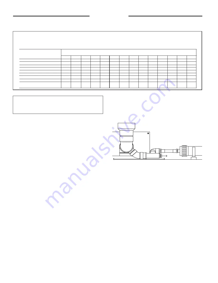
CONDENSATION ELBOW ASSEMBLY
Prior to connecting the exhaust vent pipe, the
condensate elbow assembly (supplied, but not
factory installed) must be connected to the ex-
haust pipe on the water heater (See Figure 2).
The free end of the 3 x 3 x 1.5 PVC reducing tee
slip fits over the 3” exhaust pipe on the water
heater. For maximum durability and sealing, use
a high heat silicone sealant appropriate for di-
rect vent appliances (rated for at least 150° F).
Apply a bead of silicone around the inside of
the free end of the reducing tee. Do the same
around the end of the exhaust pipe on the
heater. Push the end of the reducing tee onto
the exhaust pipe as far as the tee allows. The
orientation of the condensate elbow assembly is
critical for proper venting of gas and drainage of
condensate. See Figure 3 for proper final orien-
tation of the assembly.
INSTALLATION OF A CONDENSATE
NEUTRALIZER AND PUMP
(
Not Supplied
)
Installation
At a minimum, use 1 1/2" pipe for GHE119/125-500
TABLE 3
For U.S. Installations
Maximum Capacity of Pipe in Cubic Feet of Gas per Hour for Gas Pressures of
0.5 psig or Less and a Pressure Drop of 0.3 Inch Water Column
Based on a 0.60 Specific Gravity Natural Gas; If 1.5 Specific Gravity L.P. Gas is used, multiply capacity by 0.63
Nominal Internal
Iron Pipe Size
Diameter
Inches Inches
10
20 30 40 50 60 70 80 90 100 125 150 175 200
1/2
.622
132 92 73 63 56 50 46 43 40 38 34 31 28 26
3/4
.824
278 190 152 130 115 105 96 90 84 79 72 64 59 55
1
1.049
520 350 285 245 215 195 180 170 160 150 130 120 110 100
1
1/4
1.380
1,050 730 590 500 440 400 370 350 320 305 275 250 225 210
1
1/2
1.610
1,600
1,100 890 760 670 610 560 530 490 460 410 380 350 320
2
2.067
3,050 2,100 1,650 1,450 1,270 1,150 1,050 990 930
870 780 710 650 610
2
1/2
2.469
4,800 3,300 2,700 2,300 2,000 1,850 1,700 1,600 1,500 1,400 1,250 1,130 1,050 980
3
3.068
8,500 5,900 4,700 4,100 3,600 3,250 3,000 2,800 2,600 2,500 2,200 2,000 1,850 1,700
4
4.026
17,500 12,000 9,700 8,300 7,400 6,800 6,200 5,800 5,400 5,100 4,500 4,100 3,800 3,500
Length of Pipe, Feet
Maximum Pipe Capacity for Installations in Canada,
refer to CAN/CSA B149.1.
For Natural Gas see Tables A.1 to A.17
For Propane (LP) Gas see Tables B.1 to B..12
Figure: 2
Содержание GHE 125-500A
Страница 20: ...20 Installation Schematic Diagram Figure 18...
Страница 25: ...25 Operation Steps to adjust the setpoint temperature Figure 21...
Страница 37: ...37 Notes...
Страница 38: ...38 Notes...
Страница 39: ...39 Notes...