background image


TM005 Rheem Solar Hiline Service Instructions REV D 
D.O.I 20/02/2009 

This document is stored and maintained electronically by 


Service. All printed copies not bearing this statement in RED are deemed “uncontrolled”.


20 

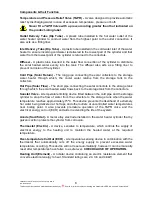
TEST 6a & 8a 

– EWT Type Thermostat 

TEST 6b & 8b 

– ST Type Thermostat 


Test  6:

  Using  a  multimeter  on  the  x1  resistance 

scale, measure between terminals 1L and 2T on the 
thermostat.  
 
The reading should be 0 ohms.  
 

Test  8: 

Same  test  points  as  test  6a  however  the 

reading should be infinity (open circuit). 


Test  6: 

Using  a  multimeter  on  the  x1  resistance 

scale,  measure  between  terminals  1  and  2  on  the 
thermostat.  
 
The reading should be 0 ohms.  
 

Test  8: 

Same  test  points  as  test  6b  however  the 

reading should be infinity (open circuit). 


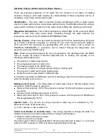
TEST 7a 

– EWT Type Thermostat 

TEST 7b 

– ST Type Thermostat 


Remove  element  wires  from  terminals  2T  &  4L  of 
the  thermostat.  Using  a  multimeter  on  the  x1 
resistance  scale,  measure  between  the  element 
terminals. 


Normal resistance for the heating unit is:  

2.4kW: 22 ohms 

– 24 ohms +/- 10% 

3.6kW: 15 ohms 

– 16 ohms +/- 10% 

           4.8kW: 11 ohms 

– 12 ohms +/- 10%.  


Remove  element  wires  from  terminals  2  &  4  of  the 
thermostat.  Using  a  multimeter  on  the  x1  resistance 
scale, measure between the element terminals. 


Normal resistance for the heating unit is:  

2.4kW: 22 ohms 

– 24 ohms +/- 10% 

3.6kW: 15 ohms 

– 16 ohms +/- 10% 

4.8kW: 11 ohms 

– 12 ohms +/- 10%  


Содержание 52S160

Страница 1: ...ted copies not bearing this statement in RED are deemed uncontrolled R Rh he ee em m A Au us st tr ra al li ia a P Pt ty y L Lt td d A AB BN N 2 21 1 0 09 98 8 8 82 23 3 5 51 11 1 52S160 52S300 SERVIC...

Страница 2: ...ram 12 Fault Finding 12 Fault Finding Charts 12 Fault Diagnosis Sequence 13 Fault Finding Chart 1 14 Fault Finding Chart 1 1 15 Fault Finding Chart 1 2 16 Electrical Insulation Testing 16 Fault Findin...

Страница 3: ...ing Regulatory Authorities to carry out effective repairs to a Solar Hiline solar water heater in the minimum of time Safety precautions or areas where extra care should be observed when conducting te...

Страница 4: ...on about the water heater to which it is attached The model number consists of 6 digits and 2 letters Water Heater Model Number 5 2 S 160 S5 Type 5 Solar Orientation 2 Horizontal Collector S NPT200 St...

Страница 5: ...at the collector connectors the hot and cold pipe Sunstat valve and all tank fittings 3 Check the condition of the insulation on the hot pipe Note In frost prone areas the hot and cold pipes are insu...

Страница 6: ...GB 20 GB 15 x RP1 32 x GB 20 Weight Kg Empty 103 161 Full 265 455 Solar Hiline Operation The Hiline solar system operates on the thermosiphon principle As water in the collector s gains heat from sol...

Страница 7: ...e thermostat will be required Refer to wiring diagrams in technical bulletin TB07 016 for wiring arrangements utilising the new ST series thermostat PPS Connectors Failed PPS connectors used to couple...

Страница 8: ...ge tank to the collectors Hot Pipe Solar Flow The short pipe connecting the solar collectors to the storage tank through which the solar heated water flows back to the storage tank from the collectors...

Страница 9: ...Note Water will expand relative to its rise in temperature The discharge from the T PR valve is usually the result of thermal expansion due to heating the quantity of the discharge will be affected b...

Страница 10: ...or the complaint the duration of the problem any change in circumstances or usage and recent weather conditions This information in conjunction with the following listed common complaints will assist...

Страница 11: ...air condensing when the collector cools down Because of high temperatures within the collector ambient air is transferred in and out of the collector through drain holes Note The collector is not herm...

Страница 12: ...up to 150 C may be present in the collector s Isolate water supply and relieve pressure through a hot tap or the temperature and pressure relief valve prior to opening the collector pipe work Wear pr...

Страница 13: ...sis Sequence Is the complaint for no hot water Have there been periods of high solar gain YES NO NO Is complaint for insufficient hot water No hot water electric booster circuit No hot water Collector...

Страница 14: ...ier Continue with diagnosis to confirm booster circuit is operational Is the booster switch turned on Turn booster on YES NO NO YES NO Is the fuse blown at the switchboard NO Isolate power and continu...

Страница 15: ...d TEST 6 YES Is the water in the tank at least 6 C lower than the thermostat setting Slide the thermostat out from under the retaining clamp and allow the base of the thermostat to cool Does the eleme...

Страница 16: ...of Active Circuit in Heater Reading not to be below 1 mega ohm 1 Connect megger leads to the active side of the terminal block and earth 2 Operate megger A reading above 1 mega ohm should be obtained...

Страница 17: ...due to insufficient roof strength NO YES The ideal collector inclination is equal to the local latitude The minimum collector inclination for the system to operate is 10 Are the collectors lying too f...

Страница 18: ...atures up to 150o C may be present in the system Isolate water supply and relieve pressure through a hot tap prior to removing any pipe work YES The tank temperature will need to be below 55o C for th...

Страница 19: ...ype Thermostat Using a multimeter on the AC voltage scale measure between active and neutral on the terminal block The voltage should be approximately 240 volts TEST 5a EWT Type Thermostat TEST 5b ST...

Страница 20: ...ale measure between terminals 1 and 2 on the thermostat The reading should be 0 ohms Test 8 Same test points as test 6b however the reading should be infinity open circuit TEST 7a EWT Type Thermostat...

Страница 21: ...leaks crossed connections or dripping taps Does the water temperature correspond with the thermostat setting YES NO NO YES Electric Booster circuit Collector circuit NO Repair any leaks Isolate cross...

Страница 22: ...if concerns surround small children or elderly occupants Has the ECO tripped NO Isolate power before continuing diagnosis Is the water temperature above 80 C Draw water until the water temperature dr...

Страница 23: ...thermostat is not tripped Is boosting required during periods of high solar gain to meet hot water demands Are there any water leaks around the collectors or heater Is the leak discharge from the T P...

Страница 24: ...tom of the collector Is the system in an area that is prone to frost Replace the collector Replace the collector No warranty applies if leak is due to frost Is the leak from the heating unit gasket Re...

Страница 25: ...ly evident when electric heating cycle is on NO YES Noise is caused by FLASH STEAM Refer to explanation in Hot Water Physics section Is the noise water hammer NO Refer to water hammer explanation in c...

Страница 26: ...ater 3 Relieve pressure from the water heater through the temperature and pressure relief valve 4 Remove the access cover and disconnect the wiring from the terminal block undo the conduit terminator...

Страница 27: ...screws retaining the collector to the angle bracket disconnect the retaining strap at the top of the collector slide the collector out and remove to ground level 5 Reassemble in reverse order of above...

Страница 28: ...ode level refit the cold pipe to the collector and fit the spring clip into place 3 Fit anode bar to anode completely unscrew and withdraw the anode carefully using the bar to counter balance the anod...

Страница 29: ...ly If the T PR valve requires replacement ensure the new valve is of the correct pressure rating If the discharge temperature is above 90 C the cause must be identified Never fit a T PR valve with a r...

Страница 30: ...9 for 300 litre models the pipe kit part number is 299209 The C series collectors are shorter and wider than the NPT collectors this will require the collectors to be repositioned during the installat...

Страница 31: ...3356 2 T PR Valve 220614 12 O ring 25mm 087023 3 Access Cover 109802 13 Blanking Disc 330606 4 Thermostat 052012 14 M33 Male Brass Nut 063602 5 Thermostat Holding Clamp 102501 15 Single Collector Supp...

Страница 32: ...Valve 220614 12 O ring 25mm 330171 3 Access Cover 109802 13 Blanking Disc 330606 4 Thermostat 051350 14 M33 Brass Male Nut 063602 5 Thermostat Holding Clamp 102503 15 2 Collector support angle 191613...

Страница 33: ...Service Agent or the Rheem Australia Water Heaters Service Department b Where it is found there is nothing wrong with the water heater where the complaint is related to excessive discharge from the te...

Страница 34: ...ED are deemed uncontrolled 34 Document Revision History Title Rheem Solar Hiline Service Instructions Document Number TM005 Revision Details of change D O I A Service Instructions issued for 52S serie...

Отзывы: