background image

HN-1010/1510 

Flow Control Indicators 

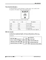
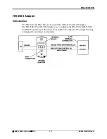
The HN-3500 has flow control indicators for testing and as a way to quickly check 
the operation of the adapter. Refer to the illustration below. 


The table below describes the function of each LED. 


Name Color 

Description 

TXD Red  Transmit 

Data 

RXD Red  Receive 

Data 

DTR 

Red 

Data Terminal Ready 

CD Red Carrier 

Detect 

PWR 

Green 

Continuous DC power is applied 

DB-9 Connector 

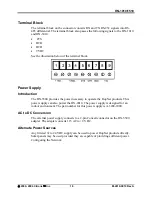
The HN-3500 is equipped with a DB-9 connector to link the RS-232 interface to a 
terminal block for the RS-485 interface. See the following illustration for the signal 
description. 


©

 2000- 2004 Cirronet

 Inc 

15 

M-2410-0010 Rev A 
Содержание HN-1010

Страница 1: ...HN 1010 HN 1510 Outdoor Indoor Units User s Guide ...

Страница 2: ...e same information Any other mode of operation using this antenna is forbidden Notice to users installers using the following fixed antennas with Cirronet RF products Andrews 24dBi parabolic dish Andrews 18dBi parabolic dish Cushcraft 15dBi Yagi Mobile Mark 14dBi Corner Reflector Mobile Mark 9dBi Corner Reflector The field strength radiated by any one of these antennas when connected to Cirronet R...

Страница 3: ...on States Norway Switzerland Use of the WIT2410 in France When used in France the WIT2410 can only be operated with the France hopping pattern selected This is accomplished by setting the pe parameter to 1 Refer to European Union Settings in this manual for details Canadian Department of Communications Industry Canada IC Notice Canadian Department of Communications Industry Canada IC Notice This a...

Страница 4: ...duction 5 Data Transmission 5 Jumper Settings 6 Power Connection 7 Antenna Connection 7 Technical Specifications 8 General 8 Mechanical 9 Environmental 9 HN 1510 Outdoor Base Remote Station 10 Introduction 10 Data Transmission 10 LED Status 11 Power Connection 11 Antenna Connection 11 Technical Specifications 12 General 12 Mechanical 13 Environmental 13 HN 3500 Adapter 14 Introduction 14 Flow Cont...

Страница 5: ...ngth Indicator RSSI 41 Set Point to Point Direct Mode 41 Set Range Optimization 42 Protocol Commands 43 Set Alternative Frequency Band 44 Set Hop Duration 44 Set Minimum Data Length 44 Get Maximum Data Length read only 44 Set Maximum Number of Remotes base only 44 Set Packet Attempts Limit 45 Set Data Transmit Delay 45 Set Slot Assignment Mode base station only 45 Set Base Slot Size base station o...

Страница 6: ...53 Introduction 53 Transceiver Requirements 53 Common System Problems 54 Guidelines for Reducing Interference 55 Introduction 55 Guidelines for Setting Up the Network 55 Guidelines for Selecting Your Site 55 Guidelines for Avoiding Terrain Obstructions 56 Customer Support 57 Introduction 57 Technical Assistance 57 Factory Repairs 57 Warranty 58 Notes 59 ...

Страница 7: ...ndustrial environments All Hopnet products work with each other and can be mixed and matched in a single network All HopNet Products are WIT2410 compatible and can be used with the WIT2410 OEM based products as well as with the SNAP2410 10Base T access point The HopNet family consists of the following products External Antenna HN 210X Base Remote Unit HN 510 Indoor Base Remote Station HN 1010 Outd...

Страница 8: ... Use transparent ARQ protocol Use same hardware for all supported data rates Supports up to 230 Kbps asynchronous data rates Full Duplex Stores setup configuration in nonvolatile memory FLASH Provide fast acquisition less than 2 seconds is the typical time to acquire hopping pattern Use smart power management features 2000 2004 Cirronet Inc 2 M 2410 0010 Rev A ...

Страница 9: ...E Data Communications Equipment A device that receives data in the form of digital signals at its input The modem side of a computer to modem connection DCD Data Carrier Detect DTE Data Terminal Equipment A device that provides data in the form of digital signals at its output The computer side of a computer to modem connection EIRP Effective Isotropic Radiated Power ISM Industrial Scientific or M...

Страница 10: ...he fade resistant HopNet frequency hopping technology employs up to 75 channels and switches channels over 100 times a second to achieve high reliability throughput HopNet Data Integrity An on board 3 KB buffer and error correcting over the air protocol ensure data integrity even in the presence of weak signals or jammers The serial interface handles both data and control of asynchronous data rate...

Страница 11: ... repeat requests ARQ and acknowledgments inside the radio are transparent to the user equipment User data rates of 230 Kbps are supported with built in CRC ARQ error protocols See below for jumper settings The HN 3500 adapter can be used to adapt RS 232 signals to RS 485 in situations where long data cable runs are required The HN 1010 uses a 9 pin Conxall weatherproof connector for power data and...

Страница 12: ...cover Remove jumpers from JP6 JP8 JP9 JP10 and JP14 Re install jumpers on pins J11 J12 J13 and J15 only Replace top cover RS 485 RS 232 Jumper Configurations for the HN 1010 The RS 232 option allows the HN 1010 to operate as a true RS 232 device here is the illustration of the 9 pin Conxall connector in RS 232 option Cable End Chassis Mount 1 TXD 4 DSR 7 DCD 2 RTS 5 CTS 8 VCC 3 RXD 6 DTR 9 GND RS ...

Страница 13: ...tenna Be sure to strictly follow the antenna manufacturer s installation instructions for proper operation of the antenna Be sure that you use the proper polarization for a gain type antenna If you orient the antenna with wrong polarization a signal reduction of greater than 20 dB could result Use a low loss RF feedline between the antenna and the HN 1010 Make the feedline as short as possible to ...

Страница 14: ...C Part 15 203 European Community ETS 300 328 Compliance Data Rate Up to 230 Kbps Async Throughput RF Channel Data Rate 460 Kbps Serial Data Interface RS 232 RS 485 Async Network Protocol ARQ Elastic TDMA E TDMA Connector 9 pin Conxall 4282 9PG 300 Mating Connector 3282 9SG Sxx TX Power Output 18 dBm Receive Sensitivity 93 dBM RF Bandwidth 750 KHz Modulation Type GMSK Output Impedance 50 Ω Input Po...

Страница 15: ...A 4X Standards IP66 Antenna Connector TNC RF Size 5 6 in x 2 09 in x 8 39 in 142mm x 53mm x 213mm Weight 1 8 lb 816 5 g Environmental Specification Value Temperature 30 to 70 C Humidity 95 at 40 C Non condensing 2000 2004 Cirronet Inc 9 M 2410 0010 Rev A ...

Страница 16: ...f 300 to 1000 feet indoors with obstructions You can extend this range by adding a HopNet Repeater HN 2010 or using gain antennas The automatic repeat requests ARQ and multinode protocol are transparent to the user equipment User data rates of 230 Kbps are supported with built in CRC ARQ error protocols Data signals are EIA RS 232 standard for Data Communications Equipment DCE devices Data and con...

Страница 17: ... to 24 VDC Power connects to the 2 pin connector on the front panel of the transceiver A polyfuse is on the transceiver board to protect against short circuits Antenna Connection The RF signal is brought in on a standard female TNC jack connector located on the front panel Use the following guidelines when installing the antenna Strictly follow the antenna manufacturer s installation instructions ...

Страница 18: ...Japan Canada Approvals US FCC Part 15 203 European Community ETS 300 328 Compliance CE Marked Data Rate Up to 230 Kbps Async Throughput Channel Data Rate 460 Kbps Serial Data Interface RS 232 Async Network Protocol ARQ E TDMA TX Power Output 18 dBm Receive Sensitivity 93 dBm RF Bandwidth 750 KHz Modulation Type GMSK Output Impedance 50 Ω Antenna Connector TNC RF Jack Input Power at Connector 9 VDC...

Страница 19: ...m x 145mm x 51mm Weight 1 6 lb 726 g Data Connector DB 9 Receptacle 2 pin Power Connector Conxall 1728822PG 300 Mating Connector Conxall 16282 2SG 3xx Environmental Specification Value Temperature Range 30 to 70 C Humidity 95 at 40 C Non condensing 2000 2004 Cirronet Inc 13 M 2410 0010 Rev A ...

Страница 20: ...used with an RS 232 to RS 485 adapter the HN 3500 The HN 3500 enables you to configure the HN 1010 and HN 3010 for RS 485 operation yet drive them from an RS 232 controller The adapter housing is designed for an indoor environment 2000 2004 Cirronet Inc 14 M 2410 0010 Rev A ...

Страница 21: ...unction of each LED Name Color Description TXD Red Transmit Data RXD Red Receive Data DTR Red Data Terminal Ready CD Red Carrier Detect PWR Green Continuous DC power is applied DB 9 Connector The HN 3500 is equipped with a DB 9 connector to link the RS 232 interface to a terminal block for the RS 485 interface See the following illustration for the signal description 2000 2004 Cirronet Inc 15 M 24...

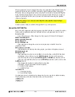
Страница 22: ...t products This power supply can also power the HN 2010 The power supply is designed for an indoor environment The part number for this power supply is A 3200 1000 AC to DC Conversion The external power supply connects to a 2 pin Conxall connector on the HN 3500 adapter The adapter converts 115 AC to 9 VDC Alternate Power Sources Any filtered 9v to 24 VDC supply can be used to power HopNet product...

Страница 23: ...tware package that runs under Windows 95 98 NT 2000 XP This chapter provides the information you need to configure your network Five Command Types The WinCom24 software enables you to configure five types of commands Serial Interface Commands Network Commands Protocol Commands Status Commands Memory Commands 2000 2004 Cirronet Inc 17 M 2410 0010 Rev A ...

Страница 24: ...ll radios support all the functions and features of every Cirronet radio Thus some selections in the Wizard will be grayed out if they are not applicable to the radio in use After detecting the serial port and baud rate of the HopNet radio the Wizard reads the settings of the HopNet radio that is connected to the PC and will display them in the various parameter windows In the bottom left corner o...

Страница 25: ...the request of Cirronet Tech Support BiDirectionalHigh 55 BiDirectionalMedium 40 ReceiveHigh 55 ReceiveMedium 40 These parameters change the color levels in percent on the RF Tools bar graphs pie charts RFToolsInterval 1000 This parameter sets the how often bar graphs pie charts will update in msec RSSIMarginal 60 RSSIPoor 80 These parameters set the levels in dBm of color the bars on the RSSI bar...

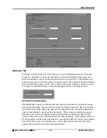
Страница 26: ...first opened but will not load them in the radio until the Apply Settings is clicked When the Apply Settings button is clicked all the changed values will be loaded into the radio even if the changed values are not on the tab currently displayed Parameters Tab The Wizard program opens the main screen with the Parameters Tab displayed The parameters screen of the Wizard allows the following variabl...

Страница 27: ...curring due to inter character gaps that are too long Refer to the section Modbus Operation for details on this mode Network Number This parameter is also known as Set Hopping and is the same command as wn Refer to Configuration Commands section for additional information on commands By using different network numbers or hopping patterns nearby or co located networks can avoid interfering with eac...

Страница 28: ...nd 1 or 2 stop bits Roaming Mode This parameter is the same as wg and allows remote radios to Roam or only link to specific base stations Protocol Mode This parameter is the same as sp and enables the base station to operate in a multipoint network Depending on the user application more or less acknowledgment may be desired by the application Remotes can operate in transparent mode even though the...

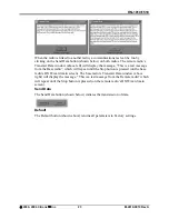
Страница 29: ...til the Stop button is pressed on the base radio s HN Wizard main screen The base radio s Transmit Data window above right will display the message This is a test message from the Remote radio which will repeat until the Stop button is pressed on the remote radio s HN Wizard main screen Send Data The Send Data button shown below initiates the transmission of data Default The Default button shown a...

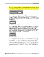
Страница 30: ...his is the pt command and when used in conjunction with the minimum data length parameter sets the amount of time from the receipt of a first byte of data from the host until the radio will transmit in transparent mode Default is 00H which causes transmission to occur without any delay When a host is sending a group of data that needs to be sent together setting this parameter will provide time fo...

Страница 31: ...elapses before sending a data packet with less than this number of bytes This parameter can be used to keep short intermittent transmissions contiguous In packet modes the length parameter in the data packet will override this value This value is subject to the maximum data length even in packet mode Set Packet Retries This is the pr command and if ARQ Mode is set to 0 it sets the number of times ...

Страница 32: ...ink time can be reduced if this value is also programmed into the remotes which use it as a starting value when scanning for the base The speed at which the radio hops affects both latency and throughput The faster the radio hops the shorter the latency but the lower the throughput The minimum packet length and packet timeout allow fixed length packets of data to be transmitted on a single hop wit...

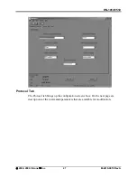
Страница 33: ...0 Protocol Tab The Protocol tab brings up the configuration screen above On the next page are descriptions of the commands parameters that are available for modification 2000 2004 Cirronet Inc 27 M 2410 0010 Rev A ...

Страница 34: ...ll change depending on the frequency band the radio operates in For 2 4GHz radios selecting one of the 802 11b bands in which to operate the HopNet radio can be used in locations with 802 11b networks without causing interference with those networks If there are no 802 11b networks present it is recommended that the radio be set to operate in the entire band which is the default For 900MHz radios ...

Страница 35: ...erating as remote radios The radio must be linked with its base radio for the functions on this screen to work Range Optimization HopNet 2410 based radios only This command automatically applies an adjustment factor to the over the air timing of remotes to compensate for the effects of propagation delay at long ranges Simply click on the radio button opposite Range Optimization and the following s...

Страница 36: ...ce between radios and click OK A bar will appear showing the progress of Range Optimization Once the process has completed the Range Optimization radio button will clear and the Done radio button will fill in indicating that adjustment factor has been applied 2000 2004 Cirronet Inc 30 M 2410 0010 Rev A ...

Страница 37: ...e Only percentage above 95 and the Bi Directional percentage above 90 These functions operate with the Automatic Retransmit Request ARQ disabled and as such provide an indication of link quality but do not provide an indication of how often data will get through since in normal operation ARQ is enabled and the radio automatically and transparently will resend data that was not received on the firs...

Страница 38: ...low 80 will display red Bars at levels between these two points will display yellow These points can be modified by editing the INIT INI file Under normal operation the received signal strength for each channel will fluctuate occasionally dropping to nothing indicating the hop was missed by the radio This display also shows multipath fading when a channel drops noticeably below the surrounding cha...

Страница 39: ...d Com Port and Baud Rate will need to be set manually NOTE In order to display the banner you will need to press the F1 key twice toggling the DTR which resets the radio and causes a new banner to display WinCOM de asserts and re asserts the DTR line to the radio which resets the radio causing the sign on banner to be displayed as shown below The banner indicates the radio firmware version whether...

Страница 40: ...al line in the COM port The radio is normally in data mode data that is sent to it from the PC is transmitted over the wireless connection When the WinCOM window is active keys typed on the keyboard will be sent to the radio and will be transmitted Unless the Echo box is checked the typed data will not be displayed in the WinCOM window of the sending radio To change configuration parameters the ra...

Страница 41: ... to the Configuration Commands section below for details on all the configurable parameters When the radio is linked to another radio a communications test can be run by clicking on the Transmit button or pressing the F6 key Whatever ASCII string is in the Transmit String window will be transmitted as shown below If the other radio is sending data the received data will be displayed in the WinCOM ...

Страница 42: ...rt to next higher value Value is displayed in status line Useful when WinCOM is used to change the interface data rate WinCOM can communicate at new data rate without having to exit and re enter WinCOM PgDn Sets data rate of PC serial port to next lower value Value is displayed in status line Recover When the Wizard program is opened it reads the parameters of the HopNet radio connected to the PC ...

Страница 43: ...ard can be saved for future use The Wizard prompts to save changes on initial boot up after changes have been applied and on exiting the Wizard if the changes have not previously been saved The default filename for the configuration settings is hn_xxxxxx cfg where xxxxxx is the serial number of the radio in the HopNet This serial number is also on the outside of the radio To save a configuration u...

Страница 44: ...nds which set a parameter also have a option which causes the modem to respond with the current parameter setting e g wn Each modem command must be followed by either a carriage return or a line feed Serial Commands These commands affect the serial interface between the modem and the host The default settings are 9600 bps and protocol mode 0 Command Description sd 00 FF Set Data Rate Divisor Data ...

Страница 45: ...on integer values down Set Protocol Mode Enables the base station to operate in a multipoint network Depending on the user application more or less acknowledgment may be desired by the application Remotes can operate in transparent mode even though the base station is operating in one of the nontransparent modes When using a protocol mode make sure to count in packet overhead when calculating netw...

Страница 46: ...t Hopping Pattern Network Number 0 default wp 0 1 Set Transmit Power 0 10mW 1 100mW default wr Read Receive Signal Strength remote only wu 0 1 Set Point to Point Direct Mode 0 Multipoint mode default 1 Point to point direct mode dx 0 FF remote only Set Range optimization 0 default Set Transceiver Mode Sets modem operation as either base station or remote Default is remote Set Default Handle This h...

Страница 47: ...p they would be on different frequencies Set Transmit Power The HopNet has two preset transmit power levels 10mW 10dBm and 100mW 20dBm Control of the transmit power is provided through this command Default is 100mW Read Receive Signal Strength Indicator RSSI This command reports the relative signal strength averaged over the last 10 hops This command returns a one byte value that is proportional t...

Страница 48: ...i x dx 1 33km 0 17km x dx The following table presents various values of dx and the associated optimal and max ranges dx setting range min optimal max 00H 0mi 0km 0 1mi 0 2km 0 8mi 1 3km 01H 0mi 0km 0 2mi 0 3km 0 9mi 1 5km 04H 0mi 0km 0 5mi 0 8km 1 2 mi 2 0km 06H 0 1mi 0 2km 0 7mi 1 2km 1 4mi 2 3km 09H 0 4mi 0 7km 1 0mi 1 6km 1 8 mi 3 0km 13H 1 4mi 2 3km 2 0mi 3 3km 2 8mi 4 7km 31H 4 4mi 7 3km 5 0...

Страница 49: ... 01 default pl Get Maximum Data Length D4 default 212 bytes pn 01 3e base only Set Maximum Number of Remotes 3e default 62 remotes pr 00 ff Set Packet Attempts Limit 10H default FFH Infinite retry RF flow control point to point only pt 00 ff Set Data Transmit Delay 00H default pv 0 1 base only Set Slot Assignment Mode 0 default dynamic slot assignment 1 static slot assignment pw 00 34 base only Se...

Страница 50: ...ed to form a packet in transparent mode The radio will wait until the data transmit delay elapses before sending a data packet with less than this number of bytes This can be used to keep short intermittent transmissions contiguous In packet modes the length parameter in the data packet will override this value See Section 3 1 This value is subject to the maximum data length even in packet mode Se...

Страница 51: ... length of data to be sent together is longer than the time slot can send the data will not be sent together but will be broken up over multiple hops The length of time the radio will wait is equal to the specified value times the hop duration Set Slot Assignment Mode base station only Sets whether the base station will assign remote transmit slots dynamically based on the number of remotes curren...

Страница 52: ...h general interface aspects of the operation of the HopNet Command Description zb 0 1 Banner Display Disable 0 disabled 1 enabled default zc 0 2 Set Escape Sequence Mode 0 disabled 1 once after reset default 2 unlimited times zh Read factory serial number high byte zm Read factory serial number middle byte zl Read factory serial number low byte zp 0 5 base only Set the duty cycle at which the mode...

Страница 53: ...visible in the startup banner Set Duty Cycle Allows reduced power consumption by having a remote wake up only every 2N hops to receive and transmit Power consumption is roughly proportional to the duty cycle selected For example if N 2 the remote will wake up every fourth hop Power consumption will be roughly the consumption as when N 0 This parameter must be set to the appropriate value when more...

Страница 54: ...sets the HopNet to its factory default state This is useful for testing purposes or if there is a problem in operation of the system and the configuration is suspect Use the Store Memory command afterwards if you wish the factory default settings to be remembered the next time you cycle power or reset the radio Recall Memory Useful for restoring the power on settings after experimenting with tempo...

Страница 55: ...imum Data Length pn 01 3e Set Maximum Number of Remotes base only pk 00 d4 Set Minimum Data Length pr 00 ff Set Packet Attempts Limit pt 00 ff Set Data Transmit Delay remote only pv 0 1 Set Slot Assignment Mode base only pw 00 40 Set Base Slot Size base only px 0 1 Set ARQ Mode Status Commands zb 0 1 Banner Display Disable zc 0 2 Set Escape Sequence Mode zh Read Factory Serial Number High Byte zm ...

Страница 56: ...f the antenna system and reduce data streams Groups of short data streams are more reliable and have a better chance of success in the presence of interference than do long streams Systems installed in rural areas are least likely to encounter urban interference Multiple HopNet systems can operate in close proximity to each other but require a unique network address Poor quality coaxial cables wil...

Страница 57: ...re connected through a repeater See the illustration of a point to point application on the next page Point to Multipoint This common application consists of a central host and remote terminal units or other data collection devices The automatic repeat requests ARQ and acknowledgments inside the radio are transparent to the computer system 2000 2004 Cirronet Inc 51 M 2410 0010 Rev A ...

Страница 58: ...HN 1010 1510 Point to Point A point to point application as shown below provides a communication data link between two locations 2000 2004 Cirronet Inc 52 M 2410 0010 Rev A ...

Страница 59: ...izes to it If the base station has problems the entire network will be compromised This chapter provides troubleshooting information for your HopNet products Transceiver Requirements For proper operation all transceivers in the network must meet these basic requirements Adequate and stable power Secure connections Power RF and Data Proper programming especially Hop Duration and Network Address 200...

Страница 60: ...k antenna feedline connectors and reflective power 3 If remote unit is in synchronization but performance is poor it may indicate antenna problems Check for properly aligned antenna headings 4 Verify proper programming of the system parameters Interference is suspected 1 Verify that the system has a unique network address Nearby systems with same address will cause interference problems 2 If Omni ...

Страница 61: ...ich minimizes interference from stations located outside the pattern Multiple HopNet systems can co exist in close proximity to each other with very minor interface as long as they are assigned a unique network address Each network address has a different hop pattern If interference is suspected from a similar operating system change the antenna polarization This will provide an additional 20dB of...

Страница 62: ...ssociated remote sites provides for the most reliable transmission path A line of sight path can be achieved by mounting the station antenna on a tower or elevated structure that raises it to a sufficient level to clear surrounding terrain and other obstructions The importance of a clear transmission path relates closely to the distance to be covered If the system is to cover only a limited geogra...

Страница 63: ...t to the factory The following telephone numbers are available for assistance Phone 678 684 2000 Fax 678 684 2001 Factory Repairs If return of equipment is necessary you will be issued a Return Material Authorization number RMA The RMA will help expedite the repair so that equipment can be returned as quickly as possible Please be sure to include the RMA number on the outside of the shipping box a...

Страница 64: ... power failure No suit or action shall be brought against Seller more than twelve 12 months after the related cause of action has occurred Buyer has not relied and shall not rely on any oral representation regarding the goods sold hereunder and any oral representation shall not bind Seller and shall not be a part of any warranty THE PROVISIONS OF THE FOREGOING WARRANTY ARE IN LIEU OF ANY OTHER WAR...

Страница 65: ...HN 1010 1510 Notes 2000 2004 Cirronet Inc 59 M 2410 0010 Rev A ...

Страница 66: ...HN 1010 1510 2000 2004 Cirronet Inc 60 M 2410 0010 Rev A ...

Отзывы: