RF-BM-ND08
Shenzhen RF-star Technology Co., Ltd.
Page 14 of 19
5.
Assuming that the module is soldered or placed in the Top Layer, it is also wrong to randomly route the Bottom Layer
or other layers, which will affect the spurs and receiving sensitivity of the module to some degrees;
6.
Assuming that there are devices with large electromagnetic interference around the module, which will greatly affect
the module performance. It is recommended to stay away from the module according to the strength of the
interference. If circumstances permit, appropriate isolation and shielding can be done.
7.
Assuming that there are routings of large electromagnetic interference around the module (high-frequency digital,
high-frequency analog, power routings), which will also greatly affect the module performance. It is recommended
to stay away from the module according to the strength of the interference. If circumstances permit, appropriate
isolation and shielding can be done.
8.
It is recommended to stay away from the devices whose TTL protocol is the same 2.4 GHz physical layer, for
example: USB 3.0.
9.
The antenna installation structure has a great influence on the module performance. It is necessary to ensure the
antenna is exposed and preferably vertically upward. When the module is installed inside of the case, a high-quality
antenna extension wire can be used to extend the antenna to the outside of the case.
10.
The antenna must not be installed inside the metal case, which will cause the transmission distance to be greatly
weakened.
11.
The recommendation of antenna layout.
The inverted-F antenna position on PCB is free space electromagnetic radiation. The location and layout of antenna
is a key factor to increase the data rate and transmission range.
Therefore, the layout of the module antenna location and routing is recommended as follows:
(
1
)
Place the antenna on the edge (corner) of the PCB.
(
2
)
Make sure that there is no signal line or copper foil in each layer below the antenna.
(
3
)
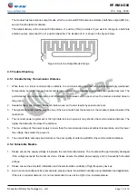
It is the best to hollow out the antenna position in the following figure so as to ensure that S11 of the module
is minimally affected.
Figure 7. Recommendation of Antenna Layout
Note: The hollow-out position is based on the antenna used.
12.
Antenna output mode change:

