RFX-RMT-II Dual Band
LAST REV: April 2008
16
Operator’s Manual
RF ExtremeCare: 866.732.0113
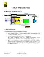
7 CIRCUIT DESCRIPTIONS
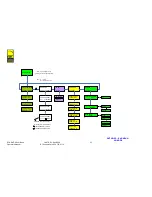
RMT-II Dual Band Simplified block diagram
COFDM modulator
Power supply
Front panel display
and push button
control
Power
amplifier
Encoder
Video/
audio
processing
MPEG coder
Power
supply
I
2
S
ASI
Transport
stream
SDI (+ embedded audio), or ASI,
or composite video
YUV, or YC video
AES audio 1, 2
Analogue audio 1, 2
Analogue audio 3, 4
AES audio 3, 4
DC in
I2C Communication Bus
RF
Tx RF Out
Digital Motherboard
PA control PCB
7.1 Audio / Video Encoder
The Encoder board consists of the following main functions:
•
SDI to Digital de-serializer. Converts the SMPTE-259M-C serial digital video input
to an 8 bit parallel digital video bus.
•
Analog to Digital Video Converter, 10 bit over sampling ADC
Takes either composite video (75
Ω
, 1v p-p) (CVBS); YC or YUV inputs in either
PAL / NTSC format and converts to an 8 bit parallel digital video bus.
•
FPGA selects the required 8 bit parallel digital video bus from either the SDI or
analog input, packets this data for input to the MPEG2 encoder. A relay is used to
route the input from the BNC (either SDI or CVBS) to either the SDI de-serializer or
the PAL/NTSC decoder.

