


RE 30543/12.10 VT-HACD-3-2X
7
/16
Hydraulics
Bosch Rexroth AG
Functional description
(continued)
Digital position measurement system
When using the VT-HACD-3-2X as closed-loop control elec-
tronics, digital position measurement systems of type SSI or
incremental can be used for recording the actual value.
Limitations of use incremental encoder
The maximum frequency of the incremental encoder input (f
G
)
of the HACD is 250 kHz. The maximum travel velocity of the
drive, the resolution (res) of the encoder system used and the
possible signal analysis by an EXE (interpolation and digitali-
zation electronics) determine the frequency.
Determination formulae
Encoder resolution with given maximum velocity:
f
G
[kHz] x EXE
Res [
μ
m] ≥
v
m
x 10
3
s
Velocity with given encoder resolution:
Res [
μ
m] x EXE x f
G
[kHz]
v
m
≤
s
10
3
Controller
If the HACD is used as closed-loop control electronics, the
“Controller” entry has to be selected in the signal linking [8].
The LCx signals constitute the command value branch, the
LFBx signals the actual value branch. [8]
As actual value signal, you can use both, an SSI encoder or
incremental encoder [2] digital measurement system or one
or several analog sensors.
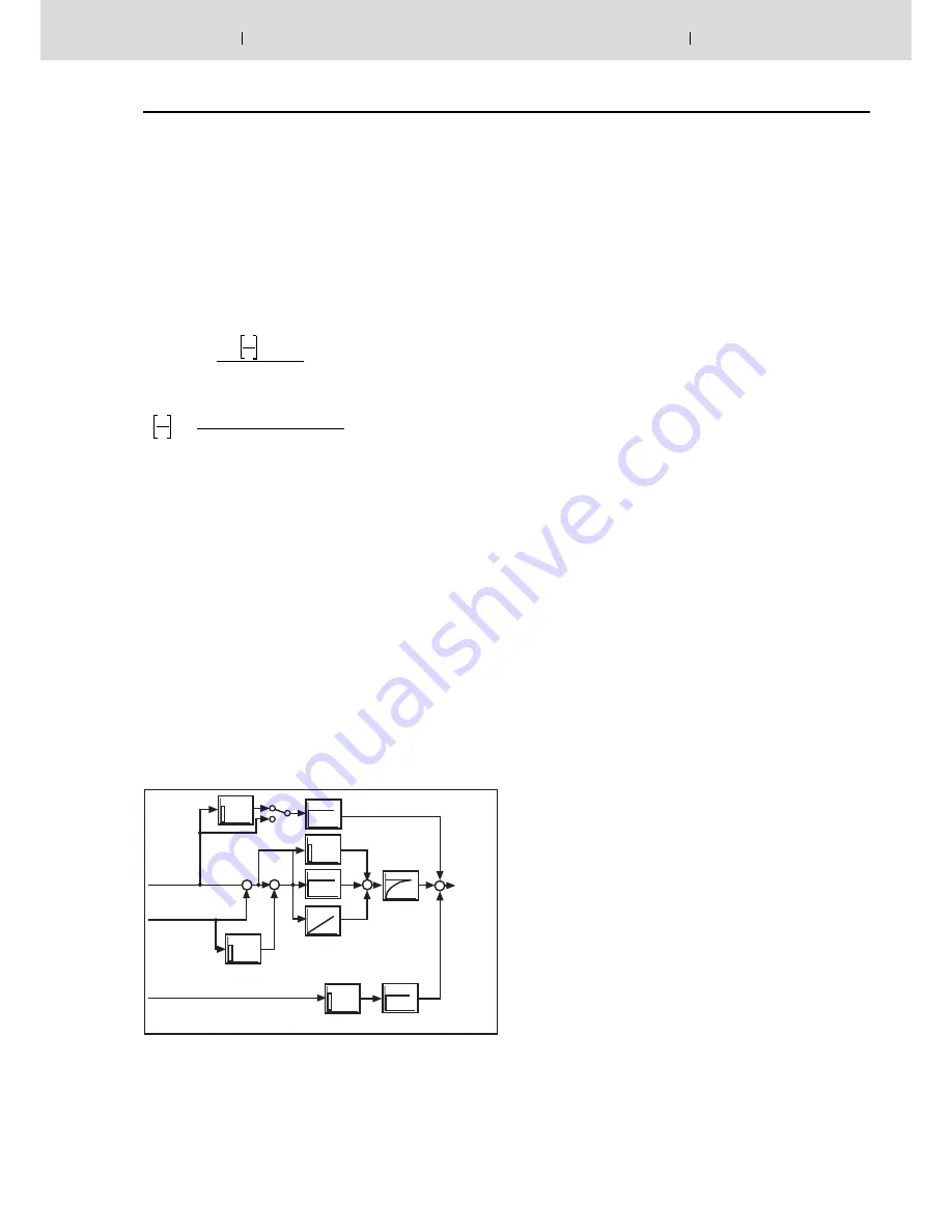
The controller structure is designed as PIDT1 controller,
whereas each component can be activated or deactivated in-
dividually. In this way, you can, e.g. also realize a P or PT1
controller. The I component can moreover be controlled via a
window (upper and lower limit).
Controller parameters can be set in a block-wise or in a block-
independent form.
A state feedback can be used for dampening the controller
output.
Controller structure:
P
I
DT1
–
–
+
+
+
–
T1
D
Adjustment to hydraulic system
For the optimum adjustment to the particularities of hydraulic
drives, the following functions are implemented upstream the
analog output:
• Direction-dependent gain [10]
For positive and negative values, the amplification can be
set separately. In this way, adjustment to the area ratio of a
single-rod cylinder is possible.
• Characteristic curve correction [11]
In this way, the progressive flow characteristic of propor-
tional directional valves is compensated or an inflected
characteristic curve is realized.
• Overlap jump/residual velocity [12]
When using valves with positive overlap, a fine position-
ing can be used in case of a PDT1 controller in order to
increase the static accuracy. This fine positioning can be
selected according to the residual voltage principle and as
overlap jump.
• Zero point correction (offset) [13]
Serves the correction of the zero point of the connected
proportional servo valve.
Error detection and troubleshooting
The HACD supports numerous error monitoring possibilities:
• Monitoring of the analog inputs for undershooting or ex-
ceedance of the range
• Monitoring of the sensors for cable break
• Control error monitoring in case of configuration of the
HACD as controller
• Monitoring of the supply voltage, all internal voltages as
well as of the +10 V reference voltage
• Monitoring of the microcontroller itself (watchdog) as well
as of the accumulator (check sum)
The error monitors as well as their reaction can be config-
ured, as well.
Command value provision
Actuation
variable
Command
value
Actual
value
Signal
DT1(actual value)
State feedback
Amplification
[ ] = Assignment to the block diagram on page 8/9


