


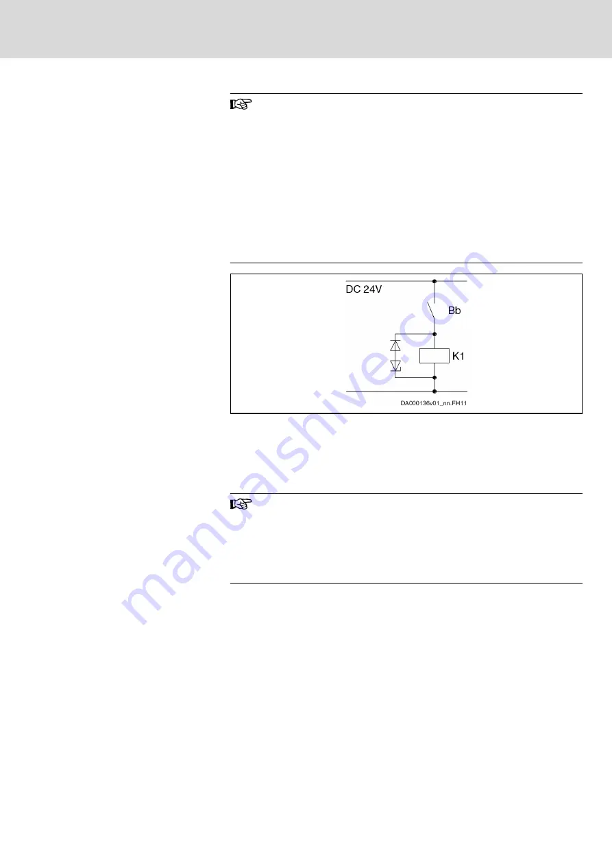
Suppressor circuit for contactor coil
When the mains contactor is switched off, the contactor coil cau‐
ses overvoltages. These overvoltages may result in premature
failure of the Bb contact.
To attenuate overvoltages, use:
●
For contactor coils with DC voltage: Overvoltage limiters with
diode combination
●
For contactor coils with AC voltage: Varistors
Avoid varistors and RC elements at contactor coils for DC volt‐
age, because varistors are subject to aging and increase their re‐
verse currents, and RC elements can overload the switching ca‐
pacity of the Bb contact.
Fig.9-1:
Recommended Suppressor Circuit
Switching on the Power Supply
Switch-on sequence
1.
Apply 24V control voltage
2.
Wait for readiness for operation of the connected components
3.
Switch on power supply (e.g. close mains contactor)
Switching off the Power Supply
When mains contactor is switched off frequently
In order to prevent the external mains contactor from being over‐
loaded by the load current in the case of frequent switch-off:
●
First switch off the drive, e.g. via drive enable in the master
communication
●
Then switch off the mains contactor
Switch-off sequence
1.
Switch drive off
2.
Switch power supply off
3.
Switch 24V control voltage off, if required
Using and Arranging the Mains
Contactor
For HCS drive controllers of the Rexroth IndraDrive C product range, use an
external mains contactor in the main connection for the circuit. Connect the
mains contactor electrically between mains filter and mains input (with
HCS03 devices and HNK01 mains filters, the mains contactor may be con‐
nected electrically before the HNK01 mains filter).
The HMV01.1 supply units of the Rexroth IndraDrive M range have an inte‐
grated mains contactor (exception: HMV01.1R-W0120 have no integrated
mains contactor and require an external mains contactor).
DOK-INDRV*-SYSTEM*****-PR06-EN-P
Rexroth IndraDrive Drive Systems with HMV01/02 HMS01/02, HMD01, HCS02/03
Bosch Rexroth AG
143/309
Circuits for the Mains Connection


