®
Spring-Set Disc Brakes
P/N 8-078-889-00
effective 01/04/13
Installation and Service Instructions for 320 Series
AAB Spring-Set Brakes
Important
Please read these instructions carefully before installing,
operating, or servicing your Stearns brake. Failure to
comply with these instructions could cause injury to
personnel and/or damage to property if the brake is
installed or operated incorrectly. For definition of limited
warranty/liability, contact Rexnord Corporation, Stearns
Division, 5150 S. lnternational Dr., Cudahy, Wisconsin
53110, (414) 272-1100.
OEM’s and subsystem suppliers, please forward these
instructions with your components to the final user.
Caution
1. Servicing shall be in compliance with applicable local
safety codes including Occupational Safety and Health
Act (OSHA). All wiring and electrical connections must
comply with the National Electric Code (NEC) and local
electric codes in effect.
2. To prevent an electrical hazard, disconnect power
source before working on the brake. If power
disconnect point is out of sight, lock disconnect in the
off
position and tag to prevent accidental application of
power to system.
3. To avoid damage to internal power supply, hipot testing
should not exceed 1500 volts for one second. Brake
coil leads must be connected together.
4. Heat developed during normal operation (135°C) of the
brake may be hot enough to be painful or cause injury.
Be careful when touching exterior surfaces. Allow
sufficient time for the brake to cool before servicing.
5. After usage, the brake will contain burnt and degraded
friction material dust. This dust should be removed
before servicing or adjusting the brake.
DO NOT blow off dust using an air hose. It is important
to avoid dispersing dust into the air or inhaling it, as this
may be dangerous to your health.
a) Wear a filtered mask or a respirator while removing
dust.
b) Use a vacuum cleaner or a soft brush to remove
dust from the brake. When brushing, avoid causing
the dust to become airborne. Collect the dust in a
container, such as a bag, which can be sealed off.
Installation
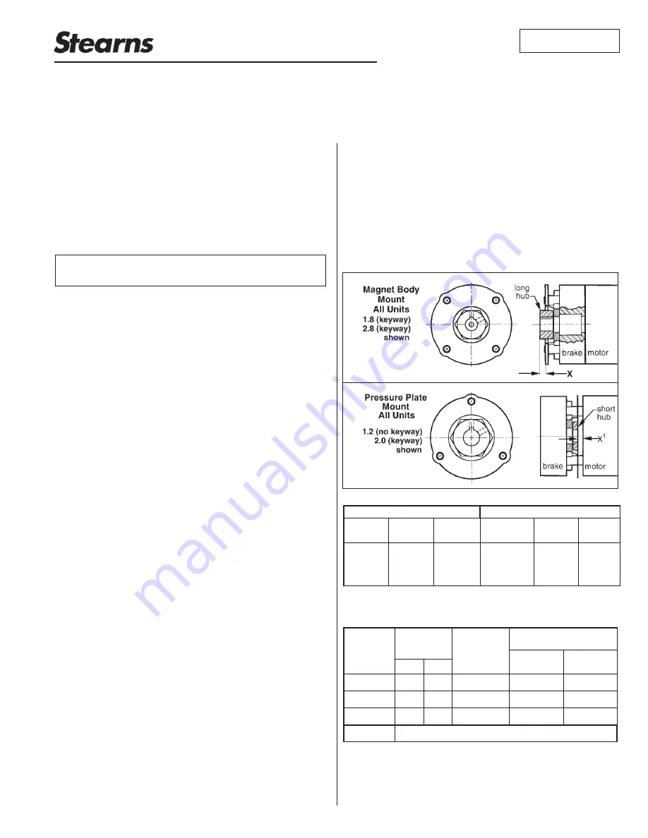
The brake can be mounted on either face. With units
mounting on the hub end, the hub should be secured to
shaft before mounting brake. Two set screws are provided
and should be tightened securely. Refer to Table A for
set screw torque. The key should not extend towards the
armature or past the face of the hub. Refer to Table B or
C for positioning of hub. Mount brake to register using
screws or bolts. Refer to Table A for mounting torque.
Lock washers are optional. The rated voltage should be
available at the brake and allowance should be made
for voltage drop in long wiring runs. The optional, factory
installed, manual release lever is a rotary maintained
design.
Note:
Position of hub should allow full engagement of
friction disc without interfering with the movement of
the armature. Motor shaft end float should be taken into
consideration when positioning the hub.
Table A
* An adapter plate is available for mounting on motors with four equally
spaced holes on a 2.844 inch bolt circle.
Table B
* This dimension is for units mounting on hub end, and using short
version of the hub. Factor in motor shaft end float; do not allow hub to
contact armature.
Angular
Parallel
.005
.005
.003 to .015
.015*
See back page
.49
2.8
2.0
.005
.005
.003 to .015
.015*
.17
1.8
.005
.005
.003 to .012
.015*
.21
1.2
Maximum Allowed
Misalignment (inches)
Operating
Range
Air Gap
(inches)
X
1
Hub
Position
(inch)
X
Size
Set Screw Torque
Mounting Screws
AAB
Size
Short
Hub
Long
Hub
Size
1.2
1.8
2.0*
2.8
9-10 lb-in
9-10 lb-in
9-10 lb-in
9-10 lb-in
9-10 lb-in
18-20 lb-in
18-20 lb-in
18-20 lb-in
#4
#6
#6
#8
Max
Torque
Min
Req
11 lb-in
20 lb-in
20 lb-in
37 lb-in
3
2
3
2


