Page 31 of 55
ILLUSTRATED PARTS MANUAL:
FLOWLINE COMB & WIRE
BINDER RANGE
SECTION 10 – SIDEFRAMES/STUB SHAFT ASSEMBLY
ALL MODELS
Removal:-
1.
Carry out previous sections where applicable.
2.
Remove back stop slide where fitted.
3.
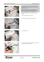
Unhook wire adjuster springs where fitted.
4.
Unscrew four off torx head screws fixing side frames to die support block and four torx head
screws fixing side frames to wire thumb wheel support.
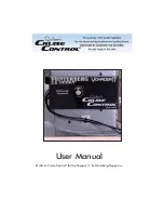
5.
Unscrew 2 off torx head screws fastening motor support bracket to side frames.
6.
Pull side frames out of engagement with punch/die assembly, punch plate/push plate assembly,
punch operating spindle assembly, wire closing adjustment assembly and wire closing jaws,
motor support bracket and electric lay spindle.
7.
Remove side margin adjuster assembly from left hand side frame.
Replacement :-
1.
Place A55216 on the stub shaft in the side frame assembly. Push 13 tooth gear(D55192) into hole in
side frame so that it mates with A55216.
2.
Locate gear box assembly (A55222) onto left hand side frame (D55115A). Fasten with M5 torx
3.
head screw
4.
Align punch/die assembly, punch plate/push plate assembly, punch operating spindle assembly
(D55195 and A55217) , wire closing adjustment assembly and wire closing jaws. where fitted, with
locations in side frames.
5.
Replace four torx head screws fixing side frames to die support block and four torx head screws
fixing side frames to wire thumb wheel support where fitted for both side frames.
6.
Refit side margin adjuster assembly to left hand side frame by pressing adjuster into housing
through slot in top edge of side frame.
7.
Refit wire adjuster springs and back stop slide where fitted
8.
Push 13 tooth spur gear (D55192) into left hand side frame (D55062A). Use timing marks to ensure
the two D55192 gears are aligned. Push electric lay shaft (D55194) through left hand gear, through
gear box assembly and then through right hand gear. It may be necessary to aid the alignment of the
operation my hand.
9.
Fix two off e-clips onto grooves in electric lay shaft.
Содержание CB345E
Страница 8: ...Page 8 of 55 ILLUSTRATED PARTS MANUAL FLOWLINE COMB WIRE BINDER RANGE CB345E Diagram ...
Страница 12: ...Page 12 of 55 ILLUSTRATED PARTS MANUAL FLOWLINE COMB WIRE BINDER RANGE MODEL CB355E DIAGRAM ...
Страница 17: ...Page 17 of 55 ILLUSTRATED PARTS MANUAL FLOWLINE COMB WIRE BINDER RANGE CB405E DIAGRAM ...
Страница 21: ...Page 21 of 55 ILLUSTRATED PARTS MANUAL FLOWLINE COMB WIRE BINDER RANGE MODEL WB705E DIAGRAM ...
Страница 47: ...Page 47 of 55 ILLUSTRATED PARTS MANUAL FLOWLINE COMB WIRE BINDER RANGE WIRING DIAGRAM 230V ...
Страница 48: ...Page 48 of 55 ILLUSTRATED PARTS MANUAL FLOWLINE COMB WIRE BINDER RANGE WIRING DIAGRAM 230V See Issue 14 ...
Страница 49: ...Page 49 of 55 ILLUSTRATED PARTS MANUAL FLOWLINE COMB WIRE BINDER RANGE WIRING DIAGRAM 115V See Issue 16 ...