background image

- 12 - 

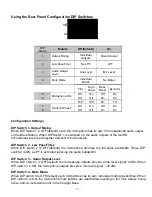
DIP Switch 5&6 – Microphone EQ: 

There are four EQ options for the microphone outputs of the Base Station. One of these options can 
be activated for both microphones.  
 

DIP Switch 7&8 - Transmit Power: 

The transmit power of the Base Station can be adjusted to help reduce the operational radius of a 
Revolabs HD

TM

 System in order to prevent interference from other Revolabs products, or from other 

devices operating in the same frequency.  


Note:


It is recommended that the lowest functioning Transmit Power be used for each system. Actual 

range depends on RF signal absorption, reflection, and interference. 

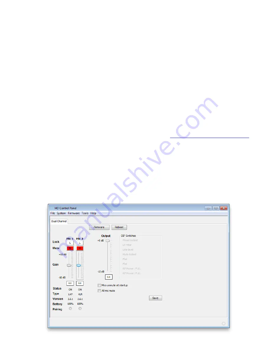
Using the Revolabs HD Control Panel Software 

A software program with graphical user interface is available for accessing control settings and real-
time status of Revolabs HD  Microphone Systems.  A detailed description of how to use this tool is 
described below. 

1.  Download the Revolabs HD Control Panel software from 

www.revolabs.com/downloads


2.  Connect the PC to the HD Single/Dual Base Station via USB.  
3.  Allow the PC to recognize the hardware and install the necessary drivers. 
4.  Install the software downloaded in Step 1, which requires Windows 2000, NT, Vista, or 7. 
5.  Launch the Revolabs HD Control Panel program. 

Configuration Settings 

The Revolabs HD Control Panel controls most of the  HD Single/Dual Base Station configuration 
settings.  It also provides real time status of the microphones. Only one HD Single/Dual system can 
be controlled and monitored from a single PC at any given time. 

Содержание 02-HDDUAL

Страница 1: ...Revolabs HD Single Dual Wireless Microphone System Models 02 HDSGL 02 HDDUAL 04 HDSGLEU 04 HDDUALEU 04 HDSGLCN 04 HDDUALCN User and Set up Guide...

Страница 2: ...art of this document may be reproduced in any form or by any means without express written permission from Revolabs Inc Product specifications are subject to change without notice Revolabs HD Single D...

Страница 3: ...sing the HD Wearable Wireless Microphones 14 Using the HD Omni Directional Tabletop Wireless Boundary Microphones 16 Using the HD Directional Tabletop Wireless Boundary Microphones 17 Using the HD XLR...

Страница 4: ...rules These limits are designed to provide reasonable protection against harmful interference in a residential installation This equipment generates uses and can radiate radio frequency energy and if...

Страница 5: ...unction with any other antenna This device complies with RF exposure requirements in Industry Canada RSS 102 Issue 4 For Body Worn Operation SAR data information for residents in countries that have a...

Страница 6: ...ction Due to the DECT frequencies used this product is licensed for operation only in the European Union countries including Australia Notice to European Customers 190 High Street Tonbridge Kent TN9 1...

Страница 7: ...ates that this product must not be disposed of with your other household waste Instead it is your responsibility to dispose of your waste equipment by handing it over to a designated collection point...

Страница 8: ...logy and ergonomic design employing Multi Carrier Time Division Multiple Access and Time Division Duplex MC TDMA TDD radio transmissions both to and from the microphone This technology allows the micr...

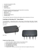
Страница 9: ...abs HD Base Station The Revolabs HD Channel Base Station shown below in front and rear panel views manages wireless audio signal processing pairing and muting between the Revolabs microphones and the...

Страница 10: ...other services to be incorporated into an application NOTE The USB port may exhibit static sensitivity If the Base Station audio shuts down after handling please power cycle the Base Station Note The...

Страница 11: ...en DIP Switch 1 is switched on the audio outputs of the two HD microphones are mixed together and sent to both outputs DIP Switch 2 Low Pass Filter When DIP switch 2 is OFF default the microphone prov...

Страница 12: ...software program with graphical user interface is available for accessing control settings and real time status of Revolabs HD Microphone Systems A detailed description of how to use this tool is des...

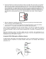
Страница 13: ...e Station If a new microphone is paired to a locked channel that microphone will then be locked as well The same goes for a locked microphone that is paired to an unlocked channel that microphone will...

Страница 14: ...crophones DIP Switches This displays the current state of the base station DIP switches When a DIP switch is in the OFF position the DIP function will remain greyed out When a DIP switch is in the ON...

Страница 15: ...2 inches 15 30cm from the mouth is recommended Make sure microphone is attached securely with the microphone LED indicator pointed up toward mouth 3 With the microphone in the wearing position un mute...

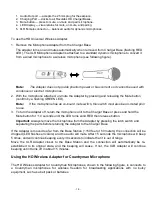
Страница 16: ...g 4 Charging port docks to Revolabs HD Charger Bases 5 Rubber feet non slip vibration absorbing pads 6 Acoustic Cover protects delicate microphone element non removable To use the HD Omni Tabletop Mic...

Страница 17: ...matically be re established to its original state and the beeping will cease If not the microphone will continue beeping until it turns off in about 15 minutes Using the HD Directional Tabletop Wirele...

Страница 18: ...button confirm by a flashing GREEN LED 4 To turn microphone off return the microphone unit to the Charger Base or press and hold the Mute button for 10 seconds until the LED turns solid RED and releas...

Страница 19: ...un muted prior to use 3 To turn the Adapter off return the microphone unit to the Charger Base or press and hold the Mute button for 10 seconds until the LED turns solid RED then release button Impor...

Страница 20: ...onds until the LED turns solid RED then release button Important Always remove the microphone from the Adapter and separate the parts before returning the Adapter to the Charger Base If the Adapter is...

Страница 21: ...old the Mute button for 10 seconds until the LED turns solid RED then release the button to turn the unit off do not release the button when you hear two beeps 2 Place the microphone unit into pairing...

Страница 22: ...nt instructions for returning and servicing non replaceable type microphone batteries For replaceable type battery microphones with serial number preference starting with either 7010 or 8020 replace o...

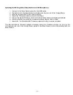
Страница 23: ...Firmware button on the Control Panel 5 Choose the desired firmware version from the location it was saved during download 6 Choose whether you would like to update the Base Station Mics or Both 7 Sele...

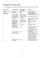
Страница 24: ...EN and RED Alternating slow GREEN and RED Microphone or channel not paired YELLOW flash alternating with GREEN flash GREEN Flashing Microphone low battery mic live YELLOW flash alternating with two RE...

Страница 25: ...gence accident or Acts of God voids this warranty The Seller shall not be liable for any consequential damage resulting from the malfunction of this product Should the user experience unsatisfactory p...

Страница 26: ...5 7dBm 37 15mW Channel spacing 1 728 MHz Modulation GFSK Class ISM Connectors Base Station Audio 3 5mm Balanced 2 In 2 Out Firmware Port Mini USB Charger Base DC power input port Proprietary 4 pin mic...

Страница 27: ...indicator 19 MC TDMA TDD 6 Microphone Charging port 13 Earpiece Jack 13 LED Display 13 Mute Button 13 Pocket Clip 13 Microphones 12 Pairing 18 Power Cord Receptacle 19 Power In Receptacle 7 Power Modu...

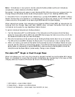
Страница 28: ...28 Revolabs HD Single Dual Manual 01 HDSGLMAN PAP 11 April 2014 Rev 2 9 Note Microphones must be fully charged for 8 hours and paired to the Base Station prior to first use...

Отзывы: