REV-11-1200-UM-02
Copyright © 2016 REV Robotics, LLC
8
2.4
PROTOTYPING AREA
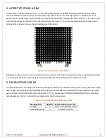
At the center of the More Board is a 16 x 16 0.1" grid prototyping area. The plated-through holes are arranged like a
standard breadboard with bus strips and terminal strips. Six bus strips run vertically with two on the left, two in the
center, and two on the right. These bus strips are electrically connected through the entire column (1 - 16). There are 16
5-pin terminal strips on each side of the center bus strips (A-E and F-J). The 5 pins are electrically connected in each
terminal strip. Figure 2-3 shows the prototyping area hole pattern.
Figure 2-3 Prototype Area Hole Pattern
By default, the bus strips are not connected to power or ground. 5.0V, 3.3V, and ground must be connected by soldering
a connection between the power pads (located at the bottom of the prototype area) and the bus strips.
2.5
MOUNTING HOLES
The More Board has 6 mounting hole locations throughout the board: 2 roboRIO mounting holes and 4 general mounting
holes. These mounting holes give flexibility in mounting the board, either mounted directly on the roboRIO or externally
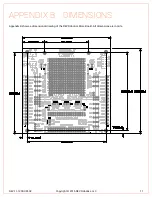
using the REV Robotics MXP Extension Cable (REV-11-1118). Please see APPENDIX B DIMENSIONS for the mounting
hole placements. Table 2-3 shows the recommended mounting screw sizes.
Table 2-3 Recommended Mounting Screw Sizes
Mounting Hole
Quantity Recommended Screw Size
roboRIO
2
4-40 x 3/16" Machine Screw
General Mounting
4
#6 Machine Screw

