background image

REV-11-1200-UM-02 

Copyright © 2016 REV Robotics, LLC 

2.3.2


SOLDER JUMPERS 

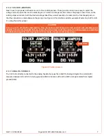
Next to each 3-pin power rail header is a set of two solder jumpers. These provide a more secure way to select the 
voltage rail, but require the use of a soldering iron. To select a voltage rail, first remove the jumper shunt. Then, on the 
solder jumper associated with the desired voltage label, flow a small quantity of solder onto the fork shaped pads so 
that the connection is made between the prongs. See Figure 2-2 for a before and after example of selecting 5.0V for DIO 
V

CC

 using the solder jumper. 


CAUTION 


Take care not to short both solder jumpers. This can create a short between the 5.0V and 3.3V rails and damage the 
roboRIO. It is also recommended that you remove the 2-pin jumper shunt when using the solder jumpers to prevent the 
accidental shorting of the rails. See Figure 2-2 for examples of proper solder jumper usage.


Figure 2-2 Solder Jumpers 

2.3.3


ANALOG SIGNALS 

The 5.0V rail is directly connected to the analog headers because the roboRIO's Analog to Digital Converter (ADC) 
measures between 0V and 5.0V. Analog ground (AGND) is broken out from the MXP and kept isolated from digital 
ground (GND). 


Solder Bead 


Содержание More Board

Страница 1: ...REV 11 1200 UM 02 Copyright 2016 REV Robotics LLC fg MORE BOARD USER S MANUAL ...

Страница 2: ... 6 2 3 POWER RAILS 6 2 3 1 JUMPER SHUNTS 6 2 3 2 SOLDER JUMPERS 7 2 3 3 ANALOG SIGNALS 7 2 4 PROTOTYPING AREA 8 2 5 MOUNTING HOLES 8 APPENDIX A SCHEMATIC 9 APPENDIX B DIMENSIONS 11 APPENDIX C BOARD REVISIONS 12 LIST OF FIGURES Figure 1 1 More Board 3 Figure 2 1 Header Pinouts 6 Figure 2 2 Solder Jumpers 7 Figure 2 3 Prototype Area Hole Pattern 8 LIST OF TABLES Table 2 1 Screw Terminal Arrangement ...

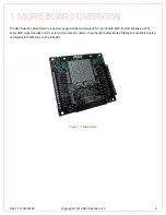
Страница 3: ...EV Robotics More Board is a passive expansion board designed for the roboRIO MXP myRIO Expansion Port Every MXP signal is broken out to screw terminals and common 3 pin headers effectively doubling the available Analog and Digital IO PWM ports on the roboRIO Figure 1 1 More Board ...

Страница 4: ... Configurable power rails o Pass through MXP 3 3V or MXP 5 0V o External power compatible Avoid brownout issues o Movable jumper shunts and solder jumpers o Separately select UART SPI I 2 C and DIO VCC sources Prototyping area o Standard breadboard style layout o 0 1 grid holes Power rail LED indicators Mounting holes o 2 holes for roboRIO mounting 4 40 x 3 16 screws o 4 holes for additional mount...

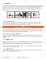
Страница 5: ...nal J2 MXP Signal 5 0V 1 16 5 0V 3 3V 2 15 3 3V DIO0 3 14 DIO11 DIO1 4 13 DIO12 DIO2 5 12 DIO13 DIO3 6 11 DIO14 DIO4 7 10 DIO15 DIO5 8 9 GND DIO6 9 8 5 0V DIO7 10 7 AIN0 DIO8 11 6 AIN1 DIO9 12 5 AIN2 DIO10 13 4 AIN3 GND 14 3 AOUT0 UART RX 15 2 AOUT1 UART TX 16 1 AGND 2 1 1 USING THE SCREW TERMINALS Using a small slotted screw driver loosen the screw at the top of the terminal you wish to use Inser...

Страница 6: ... to Servo Motors Even though 5 0V or 3 3V is provided on the middle pin of the 3 pin headers the required 6 0V is not brought out through the MXP and therefore not available on the More Board Servos must be connected to the roboRIO PWM ports 2 2 2 MXP PASS THROUGH CONNECTOR All MXP signals are routed to a female MXP header J4 at the bottom edge of the More Board Every signal is passed through this...

Страница 7: ...efore and after example of selecting 5 0V for DIO VCC using the solder jumper CAUTION Take care not to short both solder jumpers This can create a short between the 5 0V and 3 3V rails and damage the roboRIO It is also recommended that you remove the 2 pin jumper shunt when using the solder jumpers to prevent the accidental shorting of the rails See Figure 2 2 for examples of proper solder jumper ...

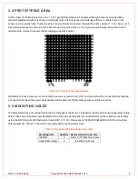
Страница 8: ...otype Area Hole Pattern By default the bus strips are not connected to power or ground 5 0V 3 3V and ground must be connected by soldering a connection between the power pads located at the bottom of the prototype area and the bus strips 2 5 MOUNTING HOLES The More Board has 6 mounting hole locations throughout the board 2 roboRIO mounting holes and 4 general mounting holes These mounting holes gi...

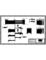
Страница 9: ...REV 11 1200 UM 02 Copyright 2016 REV Robotics LLC 9 APPENDIX A SCHEMATIC Appendix A shows the schematic for the REV Robotics More Board ...

Страница 10: ...K DIO6 SPIMISO DIO7 SPIMOSI DIO8 PWM4 DIO9 PWM5 DIO10 PWM6 AO0 AO1 UART RX UART TX DIO11 PWM7 DIO12 PWM8 DIO13 PWM9 DIO14 I2CSCL DIO15 I2CSDA 5 0V_MXP 3 3V_MXP AGND 5 0V 3 3V 3 3V 5 0V 5 0V AGND MXP_SIGNALS DIO0 PWM0 DIO1 PWM1 DIO2 PWM2 DIO3 PWM3 DIO4 SPICS DIO5 SPICLK DIO6 SPIMISO DIO7 SPIMOSI DIO8 PWM4 DIO9 PWM5 DIO10 PWM6 DIO11 PWM7 DIO12 PWM8 DIO13 PWM9 DIO14 I2CSCL DIO15 I2CSDA AI0 AI1 AI2 AI...

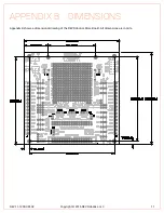
Страница 11: ...REV 11 1200 UM 02 Copyright 2016 REV Robotics LLC 11 APPENDIX B DIMENSIONS Appendix B shows a dimensional drawing of the REV Robotics More Board All dimensions are in mils ...

Страница 12: ...PENDIX C BOARD REVISIONS Version Description Date A1 Initial release 11 14 2014 B Added 5V and 3 3V power indicator LEDs Adjusted 5V rail routing to fully isolate rail when jumper is removed Added MXP pass through connector Silk screen improvements 6 7 2015 ...

Отзывы: