background image

HANDLEBAR CENTER DIRECTION

8


• 
 

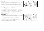
Make sure the front fork is facing forward 

(Fig.1)

.  

You may have to loosen the stem bolt a few turns using the 6mm wrench. Align the stem/handlebars with the centerline of the front wheel/tire and fork dropouts – tighten securely 

(Fig.7)

.

NOTE: 

Be sure that the minimum insertion mark on the shaft of the stem is inside the frame, it must not be visible outside of the frame 

(Fig.8)

.

WARNING!

Adjusting (or installing) the stem with the minimum insertion mark showing outside of the frame could create a dangerous condition allowing the stem to break causing
the rider to lose control resulting in serious injuries t the rider.

The stem will come installed at correct height into the fork tube and should be aligned to the center forward direction from the factory.
If adjustment is needed, use the following steps:

1

 - 

2

 - 

3

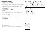
 - You may have to loosen or remove one brake pad pad to fit the wheel in the front fork 

(Fig.10)

.  When tightening or reinstalling, make sure the brake pad is aligned with the curve of the

      rim and the pad contacts the rim surface flat and evenly.

4

 -


STEP 4: FRONT WHEEL

8

Remove the plastic shipping protector from the fork dropouts and plastic axle protector(s). 
Loosen the axle nuts on the front wheel and insert the front wheel into the fork dropouts. Insert the tab of the safety washers into the small holes on the outside of the fork dropouts. 

(Fig.9)

Inspect the wheel to make sure it is centered in the fork 

(Fig.11)

. Tighten each axle nut a little at a time with a 15mm wrench, alternating between sides, until each axle nut is properly tightened.

10

9

safety 

washer

M

AX

HT

22.2

M

AX

HT

22.2

7

fork dropout 

(small hole)

brake pads

11

stem adjust

handlebar 

adjust

Содержание KODA 12

Страница 1: ...he quick release lever attached to the top of the frame seat tube outwards Insert the seat post saddle assembly into the seat tube of the frame to at least the minimum insertion line of the seat post Fig 2 Adjust the seat to your desired height Once you have adjusted the seat post to your desired height lock it in place by closing the quick release lever against the clamp Fig 3 The lever should re...

Страница 2: ...ter forward direction from the factory If adjustment is needed use the following steps 1 2 3 You may have to loosen or remove one brake pad pad to fit the wheel in the front fork Fig 10 When tightening or reinstalling make sure the brake pad is aligned with the curve of the rim and the pad contacts the rim surface flat and evenly 4 STEP 4 FRONT WHEEL 8 Remove the plastic shipping protector from th...

Страница 3: ...ench until the pedal is securely attached to the crank arm The pedals need to be tightened with a considerable amount of force so that they do not come loo se Left Pedal Locate the pedal stamped L on the end of the spindle this is the LEFT pedal Fig 12 RECOMMENDED apply a thin layer of grease to the pedal threads and insert your Left pedal into the Left side crank arm Thread it Counterclockwise an...

Страница 4: ...g 16 Squeeze the brake lever firmly several times to take the stretch out of the cable and make sure that it does not slip through its anchor If the cable tension is too tight to allow the wheel to spin freely loosen the anchor bolt and give the cable some slack If the cable has too much slack and you cannot apply enough stopping force to the rim repeat procedure 3 to take the slack out of the cab...

Страница 5: ...or floor pump with a gauge begin to inflate the tire to half its recommended inflation pressure and check to see that the tire is properly seated on the rim Be sure to inspect both sides of the tire for proper fit If the tire is seated unevenly or bulges out along the rim let some air out of the tire and reposition the tire by hand so that it sits evenly on the rim Continue to inflate the tire to ...

Отзывы: