SYSTEM OPERATION
SeaBat 8160
Operator‟s Manual
Page 36
October 6, 2011
Version 5
NOTE
The text on the BITE display will be one of the following colors:
1.
White or Green:
This feature is functioning normally.
2.
Yellow:
This feature is out of compliance or improperly calibrated.
3.
Red:
This item has malfunctioned and is no longer operational.
The BITE button is a toggle. Click the button once to activate the BITE display,
then click it again to return to the Main Sonar Display.
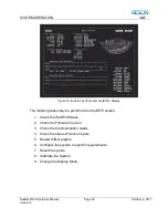
5.9.1 Ping Indicator
At the bottom left corner of the BITE screen is a small red dash that rotates 45
each time the transmit array
emits a “ping.”
Figure 17: Ping Indicator
5.9.2 Check the Wet-End Status
This item displays information with regards to the status of the sonar array
assembly.
Leak:
Shown as voltage, the leak sensor indicates the presence of
water in the sonar array. If this indicator turns red, remove the sonar
array from the water and contact a RESON Service Depot immediately.
Head Temp:
This feature is not currently enabled for the SeaBat 8160.
CtrlTemp:
Shown in degrees Celsius, this is the internal temperature of
the transceiver unit.
PwrTemp:
Shown in degrees Celsius, this is the temperature of the
transmitter power supply in the transceiver unit.
+12V:
Transceiver unit +12VDC power supply
-12V:
Transceiver unit
–12VDC power supply
TxPwr:
Transceiver unit transmitter power supply output voltage.
DipSwitch:
Shows the settings of configuration switches in the sonar
array. (This is a factory setting.)
Содержание SeaBat 8160
Страница 103: ...SYSTEM DRAWINGS SeaBat 8160 Operator s Manual Page 93 October 6 2011 Version 5 Figure 31 SeaBat 8160 System Sheet 1...
Страница 104: ...SYSTEM DRAWINGS SeaBat 8160 Operator s Manual Page 94 October 6 2011 Version 5 Figure 32 SeaBat 8160 System Sheet 2...
Страница 105: ...SYSTEM DRAWINGS SeaBat 8160 Operator s Manual Page 95 October 6 2011 Version 5 Figure 33 Array Installation Template...
Страница 107: ...SYSTEM DRAWINGS SeaBat 8160 Operator s Manual Page 97 October 6 2011 Version 5 Figure 35 Array Section 1...
Страница 108: ...SYSTEM DRAWINGS SeaBat 8160 Operator s Manual Page 98 October 6 2011 Version 5 Figure 36 Array Section 2...
Страница 109: ...SYSTEM DRAWINGS SeaBat 8160 Operator s Manual Page 99 October 6 2011 Version 5 Figure 37 Array Section 3...
Страница 110: ...SYSTEM DRAWINGS SeaBat 8160 Operator s Manual Page 100 October 6 2011 Version 5 Figure 38 Four Inch Flange...
Страница 111: ...SYSTEM DRAWINGS SeaBat 8160 Operator s Manual Page 101 October 6 2011 Version 5 Figure 39 Projector...
Страница 112: ...SYSTEM DRAWINGS SeaBat 8160 Operator s Manual Page 102 October 6 2011 Version 5 Figure 40 Hydrophone...
Страница 114: ...SYSTEM DRAWINGS SeaBat 8160 Operator s Manual Page 104 October 6 2011 Version 5 Figure 42 Cable Projector Dry End...


