background image

en

4

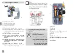
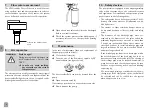
Mounting the station

10

11

12

13

10  Wall mounting bracket
11  Back half of the insulation
12  Front half of the insulation
13  Hinged controller panel


Î

Determine the mounting site of the station.


Î

Mark the drill holes by means of the template en-
closed, then drill and insert wall plugs (see fi gure 
to the right).


Î

Take the station out of the packaging. 


Î

Remove the front half of the insulation. Leave the 
pump station attached to the back half of the in-
sulation!


Î

Fasten the pump station to the wall with the en-
closed screws. For this purpose, use a crosshead 
screw driver.


Î

Fold the hinged controller panel to the left.


Î

Connect the pipework between pump station 
and store and collector respectively.

Note
All connections are already tightened such 
that they usually do not have to be tightened 
again. However, during commissioning of the 
system all connections have to be checked 
for leaks (pressure test).

Flushing and fi lling the solar 
system

WARNING!

Scald danger! 
Pressure surge damage!
If the medium enters strongly heat-
ed, empty collectors, pressure surg-
es caused by evaporation can occur.


Î

In order to prevent the solar 
fl uid from vaporising inside 
the collectors, do not fi ll 
or fl ush the system during 
times of strong irradiation!

1   Safety valve
2  Pressure gauge
3  Drain valve
4   Ball valve (return) with thermometer and 

integrated non-return valve

5  Fill valve
6 Pump
7  Grundfos Direct Sensor

TM

8   Ball valve (fl ow) with thermometer and 

integrated non-return valve

9  Air separator

5

4

3

1

2

6

7

9

8

Содержание FlowSol B HE WMZ

Страница 1: ...his RESOL product Please read this manual carefully to get the best performance from this unit Please keep this manual carefully www resol com Manual en Installation Operation Commissioning Manual for the specialised craftsman FlowSol B HE WMZ ...

Страница 2: ...qualified per sonnel named by the manufacturer Contents 1 Overview 3 2 Mounting the station 4 3 Flushing and filling the solar system 4 4 Ball valve positions 5 5 Draining the system 5 6 Non return valves 5 7 Flow rate measurement 6 8 Air separator 6 9 Maintenance 6 10 Safety devices 6 11 Accessories 7 12 Information about the pump 7 13 Lists of spare parts 7 Description of symbols WARNING Warning...

Страница 3: ...PWM2 12 power consumption of the pump 25W Safety valve 6 bar Pressure gauge 0 10bar Grundfos Direct Sensor VFS 1 12 VFS 2 40 Non return valves Opening pressure 20mbar openable Connection to diaphragm type expansion vessel ET flat sealing Outlet safety valve IT Connections to the solar pipes IT atVFS ET Maximum temperature flow return 120 C 95 C Maximum pressure 6 bar Medium Water with max 50 glyco...

Страница 4: ...ween pump station and store and collector respectively Note All connections are already tightened such that they usually do not have to be tightened again However during commissioning of the system all connections have to be checked for leaks pressure test 3 Flushing and filling the solar system WARNING Scald danger Pressure surge damage If the medium enters strongly heat ed empty collectors press...

Страница 5: ...e necessary Î Î Slowly discharge the heat transfer fluid by means of the drain valve 3 until the operating pressure is set Î Î Remove the hoses of the filling and flushing sta tion and screw the caps onto the fill and drain valves Manually start the solar thermal pump at maximum speed see controller manual and let the fluid circulate for at least 15 minutes Î Î Bleed the solar thermal system sever...

Страница 6: ...n valve 3 If necessary open the union nut at the pressure side Î Î Now dismount the pump 10 Safety devices The pump station is equipped with a diaphragm safety valve which corresponds to the relevant directives and regulations For installation and operation please pay attention to the following advice The safety valve has to be easily accessible The ef ficiency of the valve must not be influenced ...

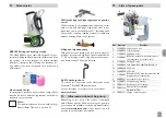
Страница 7: ...ing and flushing station The SBS 2000 has been especially designed for pro fessionally filling and flushing solar thermal and heat ing systems Its many thought out details facilitate transport operation and cleaning the attractive de sign makes it the ideal companion for a professional performance Heat transfer fluids In our product portfolio you will find a range of heat transfer fluids for diffe...

Страница 8: ...or the completeness of the drawings and texts of this manual they only represent some examples They can only be used at your own risk No liability is assumed for incorrect incomplete or false information and or the resulting damages Note The design and the specifications can be changed without notice The illustrations may differ from the original product Imprint This mounting and operation manual ...

Отзывы: