LP3-500 Owner’s Manual | 11
SYSTEM PRESSURE SWITCHES
INLET LOW PRESSURE SWITCH
System preset to shut down at inlet pressure below 15 psi
An Inlet Low Pressure Switch is installed on every Reo-Pure
System. The purpose of this switch is to prevent damage to the
pump and/or motor if there is inadequate feed water flow or
pressure.
1) Verifying Set-Point of Inlet Low Pressure Switch
To verify the setting, slowly decrease the inlet feed water
supply by slowly closing the manual inlet shut-off valve while
watching the pre-filter outlet pressure gauge. If the system
shuts down when the pressure drops to approximately 15 PSI,
then the Inlet Low Pressure Switch is functioning correctly.
2) Adjusting the Inlet Low Pressure Switch Set Point
If it is not set correctly, disconnect the power from the System
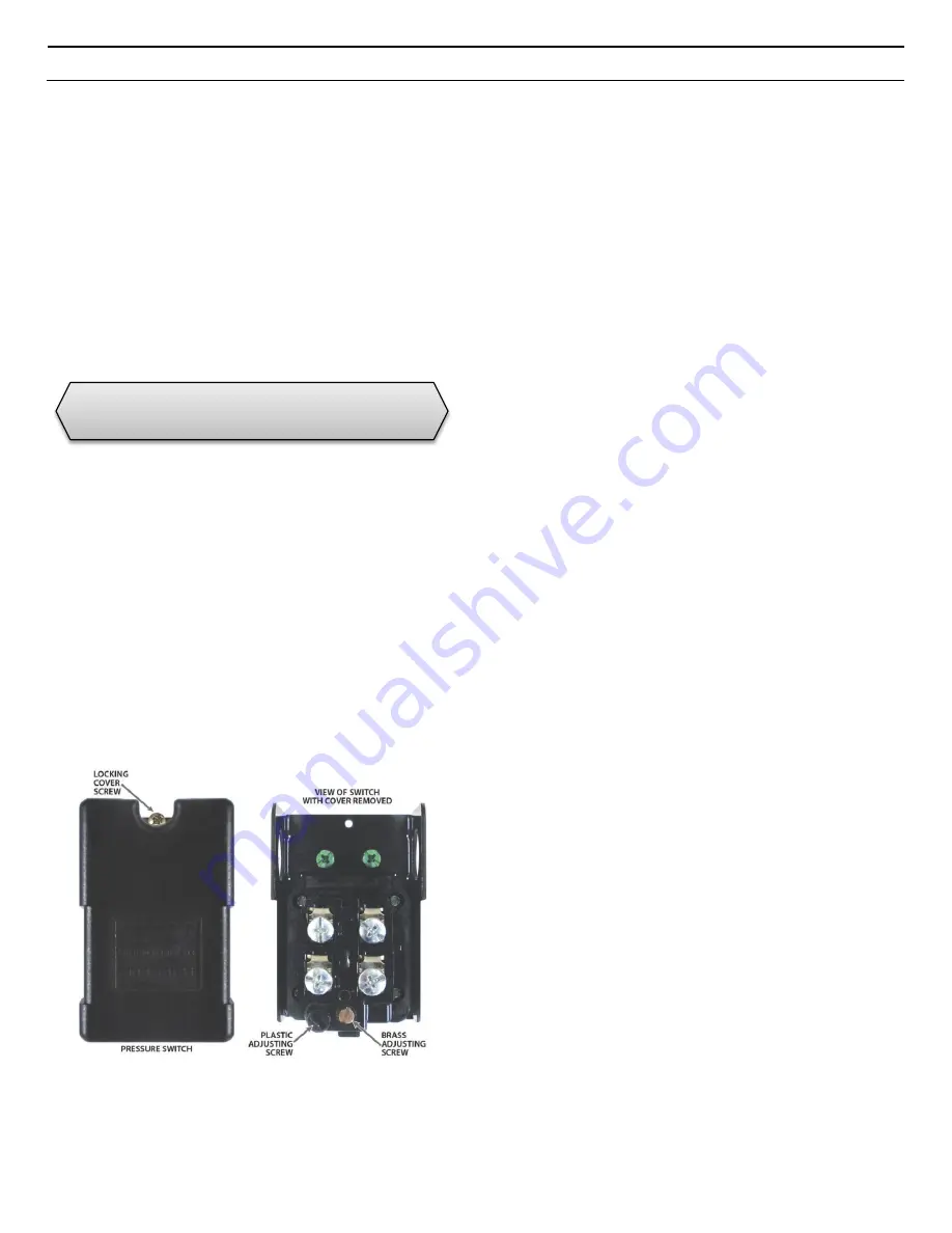
and remove the black plastic cover of the pressure switch
labeled “Inlet Low Pressure Switch”. There are two screws for
adjusting the switch settings.
Do not adjust the plastic screw.
Turn the brass screw clockwise to increase both the cut-in and
cut-out pressure. Turn it counter clockwise to decrease both
the cut-in and cut-out pressure. Turn the screw one half turn
only. Temporarily replace the cover, reconnect the power and
recheck the setting. Repeat as required.
3) Identifying a Broken Low Pressure Switch
Simply, close the inlet feed water valve, and if the System
does not shut down, the pressure switch needs replacing.
PRODUCT WATER PRESSURE SWITCH
System preset to cut-out at 45 psi and cut-in at 25 psi
A Product Water Pressure Switch is a standard feature on Reo-
Pure LP3 R.O. Systems. Its purpose is to stop and start the
R.O. system when a pressurized storage tank is used.
1) Verifying Set-Point of Product Water Pressure Switch
You will need a ball valve and pressure gauge (0-100 psi)
assembly with a tube connection the size of the R.O. system
product tubing. You will also need a container to catch the
product water.
Disconnect the power from the System. Close the pressurized
storage tank shut-off valve. Open a valve down stream of the
pressurized storage tank to relieve the pressure from the
system. Disconnect the tubing from the tank shut-off valve.
Connect the ball valve/pressure gauge assembly to this tubing.
Open the ball valve and put it into the container. Close the
down stream valve. Reconnect the power to the R.O. system.
Slowly close the new ball valve. If the R.O. system shuts
down when the pressure gauge reaches approximately 45 PSI,
the Product Water Pressure Switch is functioning correctly.
2) Adjusting the Product Water Pressure Switch
If it is not set correctly, disconnect the power to the R.O.
system and remove the black plastic cover of the pressure
switch labeled “Product Water Pressure Switch”. There are
two screws for adjusting the switch settings.
Do not adjust
the plastic screw
. Turn the brass screw clockwise to increase
both the cut-in and cut-out pressure. Turn it counter clockwise
to decrease both the cut-in and cut-out pressure. Turn the
screw one half turn only. Temporarily replace the cover,
reconnect the power and recheck the setting. Repeat as
required. When the Product Water Pressure Switch is set,
reinstall the cover and tighten the locking screw. Disconnect
the power, remove the ball valve or ball valve/pressure gauge
assembly, reconnect the System and open the tank shut-off
valve.
3) Identifying a Broken Product Water Pressure Switch
If the system does not shut down when the pressurized storage
tank is full, the Product Water Pressure Switch needs
replacing.
CAUTION
– Disconnect the power any time
the cover is removed from a pressure switch.
Содержание LP3 Series
Страница 1: ...LP3 500 Owner s Manual 0 LP3500 03172015 ...
Страница 22: ...LP3 500 Owner s Manual 21 LP3 SERIES SYSTEM FLOW DIAGRAM ...
Страница 23: ...LP3 500 Owner s Manual 22 SYSTEM WIRING SCHEMATIC ...
Страница 24: ...LP3 500 Owner s Manual 23 ...


