__________________________________________________________________________________
© Chr. Renz
MR
9/18
4.6
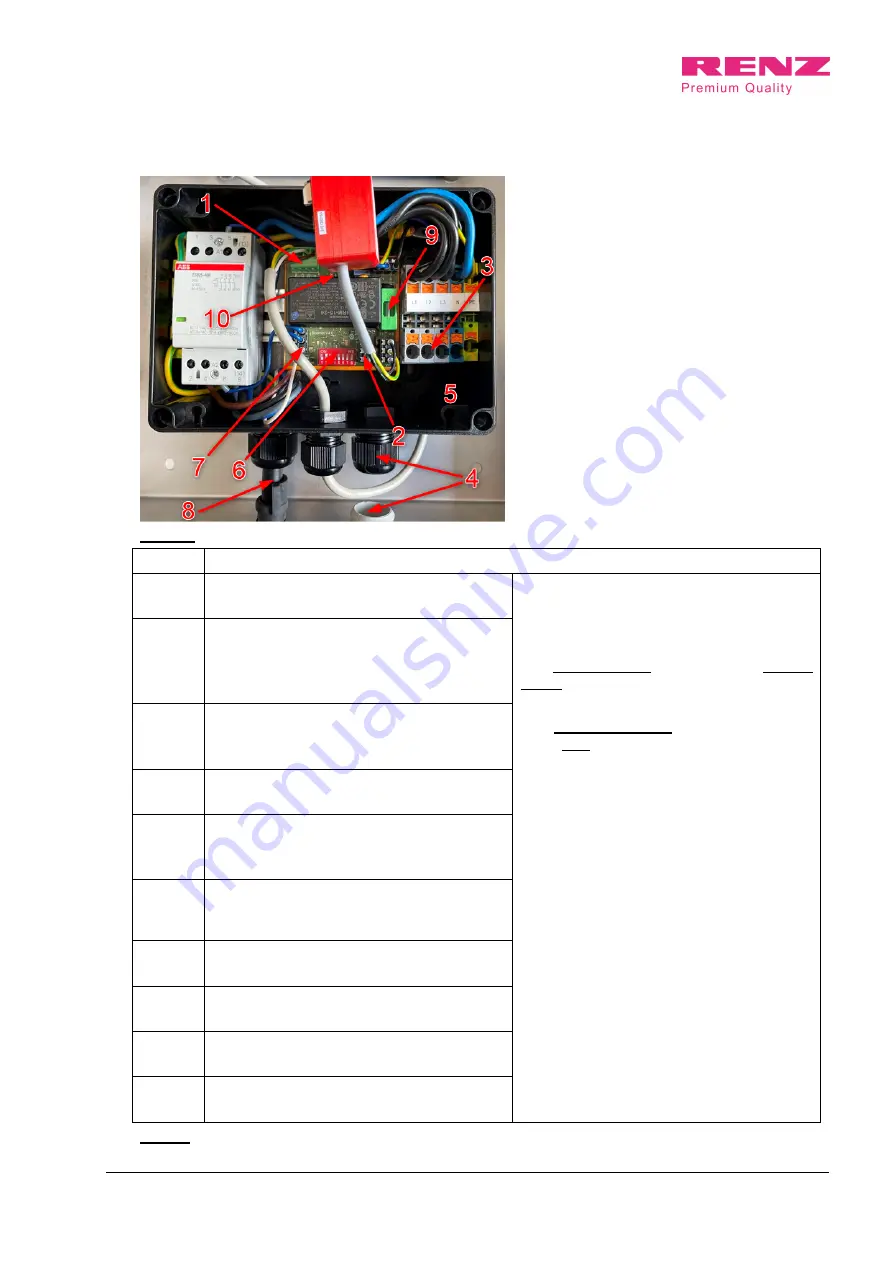
Electrical connection
Figure 6
Nr.
Description
1
Connection plug for signal lamp
(Mounted on delivery)
The supply line is inserted from below
through the cable gland. The wires are to
be clamped directly onto the terminal block.
The PE connection is made at the green -
yellow terminal.
The neutral conductor must be connected
to the blue terminal.
The three phases are connected directly to
the energy meter and connected to the
terminal block as shown in the table.
2
Enable contact
(Bridged active on delivery).
Opened: Charge release inactive
Closed:
Charging enable active
3
Mains connection
1-phase: L1, N, PE
3-phase: L1, L2, L3, N, PE
4
Cable gland
Connection cable
5
Connector plug
(Mounted on delivery.)
Fault current circuit breaker ready mounted
6
Dip switch
(Must be set according to Table 4 during installa-
tion.) (see chapter 4.8.)
7
Release from car (white wire)
(When charging plug is in the car)
8
Charging cable with type 2 plug
(Mounted on delivery)
9
Fine-wire fuse 5 x2 0
1A slow-blow
10
Communication interface K1
RS485
Table 3
.


