This is a publication by Conrad Electronic SE, Klaus-Conrad-Str. 1, D-92240 Hirschau (www.conrad.com).
All rights including translation reserved. Reproduction by any method, e.g. photocopy, microfilming, or the capture in electronic data
processing systems require the prior written approval by the editor. Reprinting, also in part, is prohibited. This publication represent
the technical status at the time of printing.
© Copyright 2016 by Conrad Electronic SE.
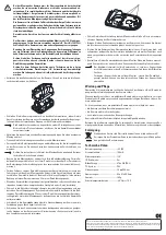
When attaching the camera, you must always take its detection range
into consideration; otherwise obstacles will not be shown or will be dis-
played inadequately. The locations at which the camera is installed must
be chosen carefully, as this affects the efficiency of the backup system as
a whole. For this reason, we recommend that you first connect the camera
provisionally and determine the final mounting location based on the image
in the monitor.
The camera should never be installed directly above the exhaust pipe or at
too low a height above the ground. Additionally, no parts of the vehicle may
be within the camera’s detection range. This would significantly affect the
rear view.
The electrical connection may be done only by a specialist.
Only a compatible monitor with a 12 V/DC output for the camera (for exam-
ple, item no. 1407922) may be used as a power source. Never connect the
camera to any other voltage supply.
Only use a volt meter, or a diode test lamp, to check the voltage of the ve-
hicle system leads, as normal test lamps consume excessive voltage and
may thus damage the vehicle’s electronics.
When installing cables make sure that the connection cables are not
squeezed or damaged by sharp edges. Use rubber bushings for penetra-
tions.
When laying cables in door frames, etc., make sure that no safety-related
equipment (such as side air bags) is affected. The cables may not be laid
within triggering range of the fully-expanded air bag.
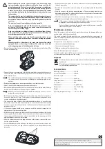
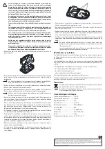
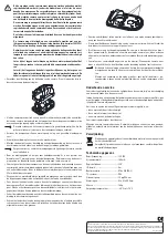
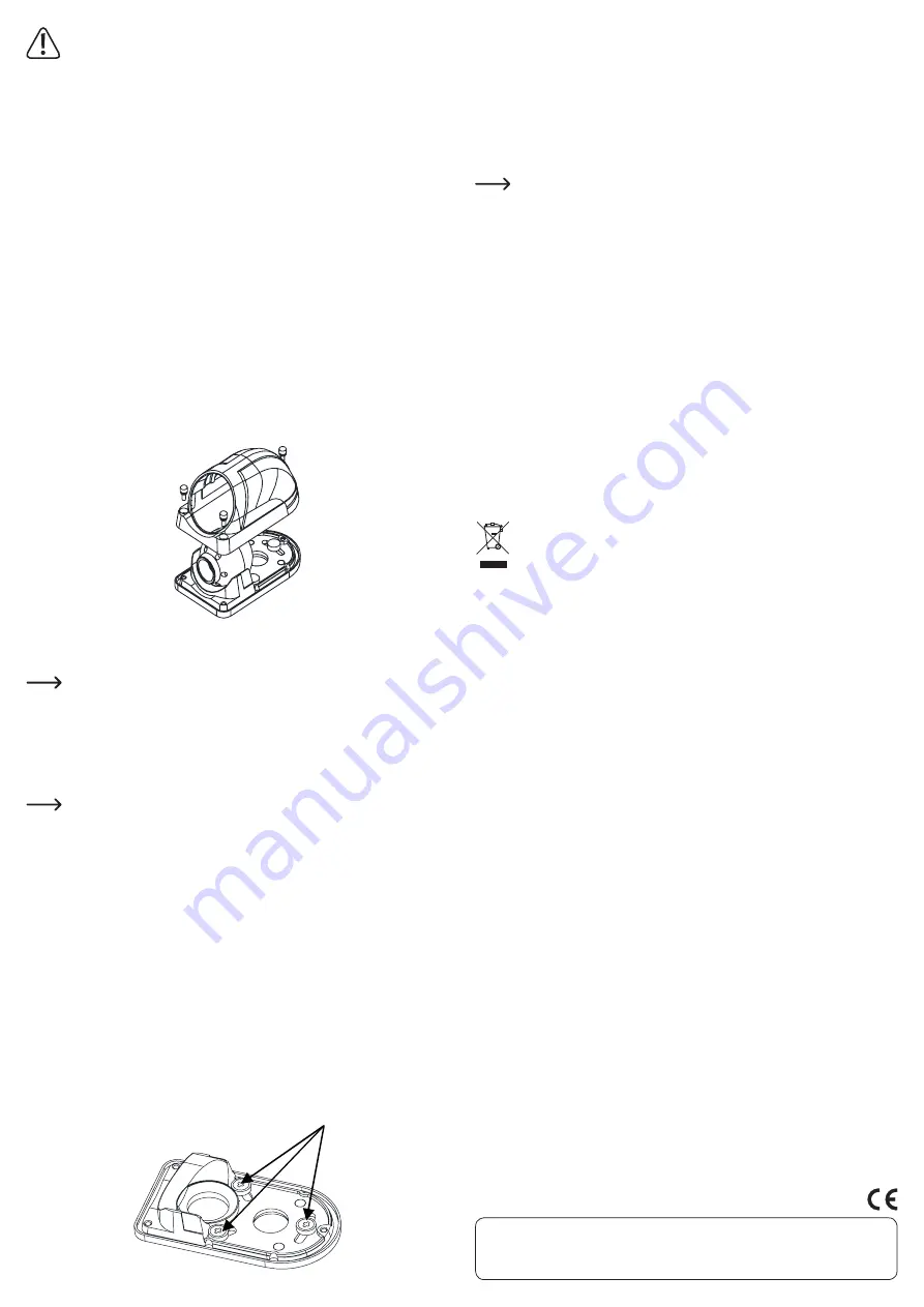
• Remove the cover from the camera housing. You do this by loosening the three Allen
screws on the housing.
• Connect the camera temporarily to the back-up monitor by connecting the camera’s
connection lead to the corresponding input on the rear view monitor using the sup-
plied extension wire.
The combination plug and their mating parts are marked with arrows. Align
the arrows to each other before assembling the combination plug-in con-
nectors.
• Activate the appropriate camera input and choose a suitable location.
• Undo the connection between camera and monitor again.
• Mark the fixing holes and the hole for the cable run on the vehicle body. You may
want to use the lower part of the housing as a template.
Make sure to leave sufficient space behind the mounting surface to accom-
modate the connecting lead.
• Drill the mounting holes and the hole for the cable entry. Cable entry requires a
hole with a diameter of 17 mm. The diameter of the mounting holes depends on the
screws used (please check dimensions).
• The connection lead is fitted with an additional rubber sleeve, in case the entry
point of the connection lead into the vehicle is not exactly situated at the mounting
location. In such a installation situation, drill another hole at the entry point with a
diameter of 22 mm.
• If the camera image should not be mirrored, insert the enclosed jumper into the
appropriate slot on the connection lead.
• Guide the camera’s connection lead through the mounting hole and possibly through
the entry point. Push the rubber sleeve into the hole of the entry point, if needed. If
the entry point of the connection lead sits directly behind the mounting point, the
additional rubber sleeve can be removed.
• Slide the rubber cover over the plug connector of the camera to protect the con-
nection against moisture.
• Fasten the bottom part of the housing to the body using the enclosed screws or oth-
er suitable screws. You can align the housing bottom in the elongated holes while
doing this.
• Guide the connection lead to the monitor and connect to the corresponding input of
the back-up monitor.
• Reattach the cover on the camera’s housing. Do not yet fully tighten the three Allen
screws.
• Align the camera to the desired monitoring range. The camera when mounted can
be pivoted and rotated. The white point on the camera lens needs to face upward or
the camera image may look distorted.
• Check the camera image on the monitor once more. Finally, when the camera is
aligned as desired, tighten the cover of the housing firmly.
If the camera is exposed to extreme brightness, objects may not be clearly
displayed. In fluorescent light, the screen may flicker.
Colours of objects shown on the monitor - especially in darkness - can differ
from the actual colours of the objects.
Maintenance and care
Check the camera’s technical safety at regular intervals, e.g., for damage to the con-
nection cables and to the camera itself.
If it can be assumed that safe operation is no longer possible, the product must be
turned off and precautions must be taken to ensure that it is not used unintentionally.
Disconnect the camera!
Safe operation can no longer be assumed if:
• the camera shows visible damage
• the camera no longer functions, or
• following considerable mechanical stress
Check the functionality at regular intervals.
Clean the camera regularly. Do not use any chemical cleaning agents, as they can
corrode or damage the material of the casing.
Disposal
Electronic devices are recyclable and must not be disposed of in the house-
hold waste!
Please dispose of the product, when it is no longer of use, according to the
current statutory requirements.
Technical data
Operating voltage............................... 12 V/DC
Current consumption ........................ 100 mA
Detection angle .................................. 120°
IR range ............................................... max. 5 m
Image resolution ................................ 976 x 582 (PAL)
TV system ............................................ PAL
Video output ........................................ 1 Vpp/75 Ohm
Dimensions.......................................... 52 x 41 x 90.5 mm
Weight .................................................. 165 g
Operating temperature range .......... -30 °C to +70 °C


