


VIONiC RESM20/REST20 angle encoder system
10
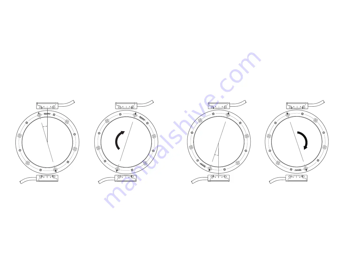
Ring orientation for partial arc applications
The partial arc DSi is based on a ring with two reference marks opposite each other. The ring must be
installed so that when the ring rotates
only
H1 can see R1 and
only
H2 can see R2.
Small angular movements
To allow the DSi to operate with very small angular movements the ring must be mounted in a certain way
in relation to the two readheads. Figure 1(a) shows how the ring must be initially mounted with reference
mark
R1
to the left of readhead
H1
. This position could be the maximum travel the ring can be rotated in an
anti-clockwise direction (limited by the user).
The angle
f
determines the minimum amount of angular movement the ring can be rotated for the DSI to
become initialised. With optimum readhead and ring positioning, the minimum angle of rotation required to
initialise a system is 3°. This is to make sure that there is enough rotational travel for both readheads to see
a reference mark. The ring will now be rotated clockwise so that H1 will see R1 and H2 will see R2, at this
point the DSI will become initialised (Figure 1(b)).
Large angular movements (< 357°)
When the DSi is used in applications where large amounts of rotation are required the ring must be installed
correctly. Figure 2(a) shows the maximum position the ring can be rotated in an anti‑clockwise direction.
Reference mark R1 must be positioned to the left of H2 so H2 will
never
see R1 upon initialisation. The
angular position
f
of R1 to H2 must again be greater than 1.5°, therefore the maximum amount of angular
movement of the ring, this being 357°.
Figure 2(b) shows the ring after it has been fully rotated in a clockwise direction to its maximum travel.
During this rotation H1 would have seen R1 and H2 would of seen R2. The DSI is now initialised.
H1
R1
R2
R2
R1
R1
R2
R2
R1
H1
H1
H1
H2
(a)
(a)
(b)
(b)
H2
H2
H2
Figure 1: Small angular movements
Figure 2: Large angular movements