


RGH40 RESR
installation guide
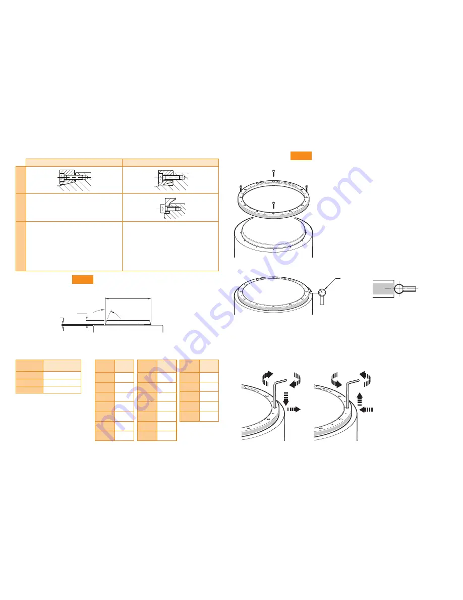
7
Select a mounting option
Taper mount
Interference fit
‘A’
section
‘B’
section
Not applicable
Notes
Recommended for all installations
Enables simplest adjustment
Offers highest accuracy
Enables eccentricity to be compensated
Offers excellent mechanical stability against
thermal cycling, shock and vibration.
Minimises cost of substrate preparation
Alternative installation
Will not correct eccentricity of the
supporting shaft
Recommended taper roundness
Recommended surface finish
≤
Ra 1.2
NOTE:
It is recommended that
the mounting surface is a turned,
rather than ground finish.
DO = Nominal external diameter
Recommended taper diameter (
DT
)
Step 2
Taper mount method
u
Clean shaft taper and internal taper of RESR as
recommended in the storage and handling section.
u
Insert the first screws:
For RESR rings with 6, 9 or 18 mounting holes,
use 3 equally spaced M3 screws.
For RESR rings with 12, 16 or 20 mounting holes,
use 4 equally spaced M3 screws.
NOTE:
Do not lubricate screws.
Recommended screw type M3 × 0.5:
ISO 4762/DIN 912 grade 10.9 minimum/ANSI B18.3.1M.
u
Insert the screws so that the RESR is loosely connected to
the shaft, then roughly align the ring by eye and touch.
u
Lightly tighten the screws. Use a Dial Test Indicator (DTI)
to check the radial displacement at the screw locations.
NOTE:
Disregard the radial displacement between the
screw locations.
u
Adjust the screws to reduce the range of radial displacement. When adjusting, identify the screw location
with the lowest radial displacement and tighten that screw, aiming for the average of the highest and lowest
indicator readings.
u
Repeat this process until the DTI readings are within ±5 µm at the screw locations.
NOTE:
It may be necessary to loosen screws whilst tightening other screws.
DTI
Use a DTI with low exertion force to avoid scratching the
scale surface. A DTI with a ruby ball stylus is recommended
as a further precaution against scratches.
NOTE
: At this stage, the screws
should only be lightly tightened
(less than 0.5 Nm)
to allow further final adjustment.
*
Allow 2 mm for 417 mm, 489 mm and 550 mm rings only
15° ±0.2°
DT
7 min
1
*
Step 1
Taper mount method
Mounting shaft specifications
Diameter
(mm)
Roundness value
(mm TIR)
≤
115
0.025
150 to 255
0.050
≥
300
0.075
DO
(mm)
DT
(mm)
52
33.85
33.65
57
40.85
40.65
75
58.85
58.65
100
83.85
83.65
103
83.85
83.65
104
83.85
83.65
115
98.85
98.65
DO
(mm)
DT
(mm)
150
133.85
133.65
200
183.85
183.65
206
189.85
189.65
209
189.85
189.65
229
212.85
212.65
255
238.85
238.65
300
283.85
283.65
DO
(mm)
DT
(mm)
350
333.85
333.65
413
395.85
395.65
417
383.85
383.65
489
454.85
454.65
550
513.85
513.65