Applications Engineering
Appendix C. Updating the RTA-FoUSB-MON
Firmware
This section discusses how to update the firmware of the RTA-FoUSB-MON hardware to function as an
In-Circuit-Debugger (ICD) and Flash-Over-USB Programmer. The ZigBee Development Kit contains an
RTA-FoUSB-MON unit that has been pre-programmed to function as an ICD. Therefore, you only need to
read this section if for some reason the ICD firmware should get corrupted and you must update the
firmware of the ICD.
The RTA-FoUSB-MON has a boot mode that can be used to program the MCU’s user Flash area. The
procedure to activate the boot mode to re-program the Flash firmware is described in the following steps.
C.1 Program the RTA-FoUSB-Mon as an In-Circuit Debugger
9. Unplug the RTA-FoUSB-MON unit from both its target and from the USB cable.
10. Remove the black plastic case.
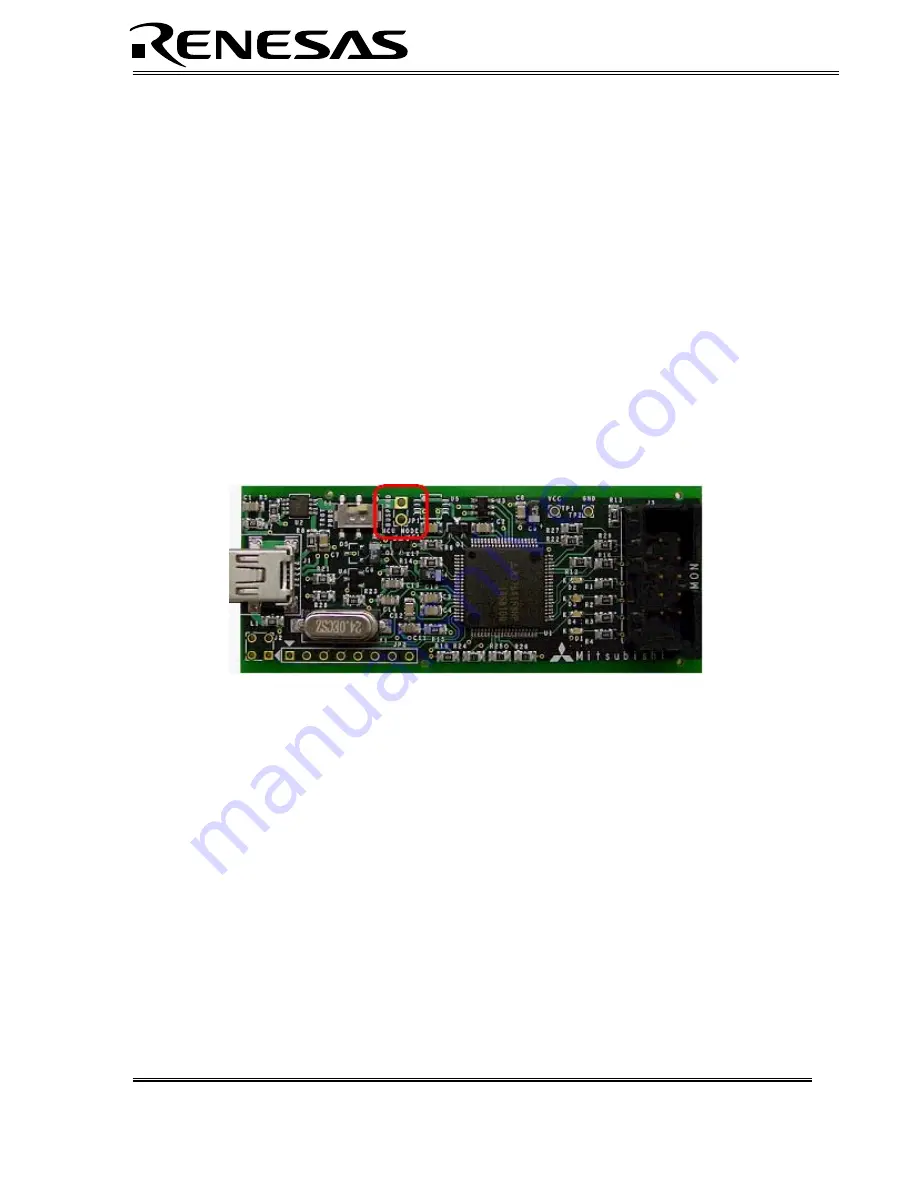
11. Shunt JP1 with a 2.54mm (0.100 mil) jumper. This will configure the ICD to run in boot mode
when it is powered up.
Figure C-2: Boot Jumper Location
12. Make sure that the power switch is set to the USB position, so that the unit is powered via the
USB bus.
13. Plug the USB cable back in. The RTA-FoUSB-MON will now be in boot mode and will
communicate as a USB device to the PC. In boot mode, the RTA-FoUSB-MON uses a different
USB Driver than the In-Circuit Debugger/Programmer application, so you will need to load
another USB Driver when doing this procedure for the first time. The Windows New Hardware
Wizard should automatically start and guide you through the installation of the required USB
driver. The driver is located in
C:\Renesas\FOUSB\USB Drivers
.
14. Open the Flash-Over-USB program. Note that the MCU device name displayed in green on the
front screen will automatically change to M37641F8 (the MCU inside the RTA-FoUSB-Mon)
without having to select that device.
15. Click on the
Load MMI
button on the right. This opens a chip selection window.
RZB-CC16C-ZDK User’s Manual Rev 1.1
29/ 39
December 2006


