TPS-1 User’s Manual: Hardware
3. Host Interface
R19UH0081ED0107 Rev. 1.07
page 30 of 86
Jul 30, 2018
3.3.2.2.
SPI Slave Interface Handshake Mode
If the header contains a read or exchange command, it is necessary to wait for a short time after transferring the header in order to enable the slave
interface to collect the data before transferring. There are two methods to do this.
You can enable the busy mode (polarity high or low) or use the wait mode.
3.3.2.2.1.
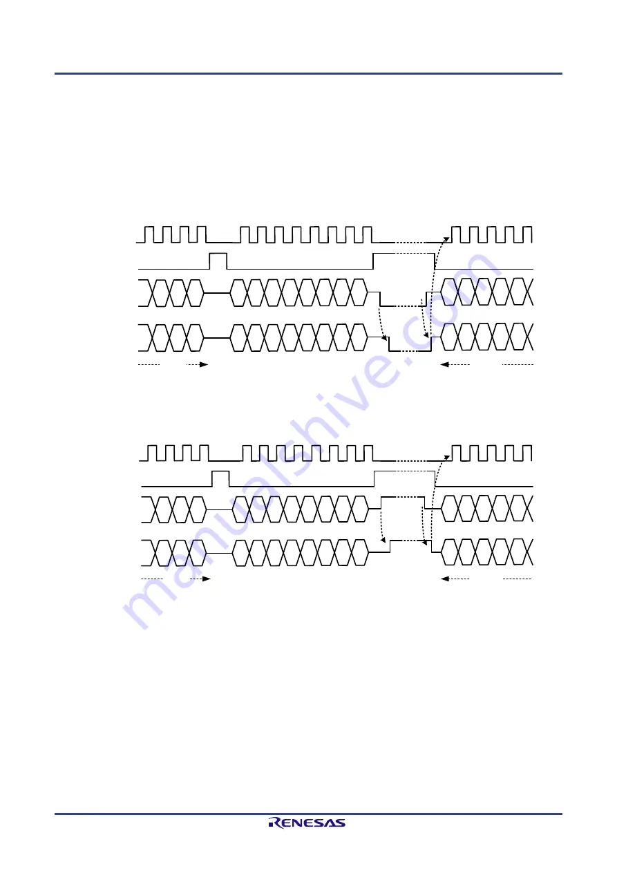
SPI Slave Interface Handshake Busy Mode
The handshake mode and the polarity can be configured with the TPS Configurator.
After transmitting the header information, the Busy_Enable signal is set (no clock and HOST_SRXD_IN in high or low – depends on the Busy_POL).
When the SPI slave interface can transmit the requested data, the
HOST_STRX_OUT
signal is set to its active level. This indicates to the SPI master
that it can start the next cycle and the master release the Busy_Enable signal. This forces the SPI slave to release the Busy level and the master starts the
next clock cycle.
B23 B22 B21 B20 B19
B17
B18
B16
HOST_SCLK_IN
HOST_SFRN_IN
HOST_SRXD_IN
B9
B10
B8
B9
B10
B8
Dummy
Dummy
Dummy
Dummy
Dummy
Dummy
Dummy
Dummy
B7
B6
B5
B4
B3
Dummy
Dummy
Dummy
Dummy
Dummy
HOST_STXD_OUT
SPI-Status
SPI-RD-Data
Busy_Enable
Busy
Motorola SPI
format:
SPO = 0
SPH = 0
Figure 3-12: SPI Read-Timing (Busy_POL=0)
B23 B22 B21 B20 B19
B17
B18
B16
HOST_SCLK_IN
HOST_SFRN_IN
HOST_SRXD_IN
B9
B10
B8
B9
B10
B8
Dummy
Dummy
Dummy
Dummy
Dummy
Dummy
Dummy
Dummy
B7
B6
B5
B4
B3
Dummy
Dummy
Dummy
Dummy
Dummy
HOST_STXD_OUT
SPI-Status
SPI-RD-Data
Busy_Enable
Busy
Motorola SPI
format:
SPO = 0
SPH = 0
Figure 3-13: SPI Read-Timing (Busy_POL=1)
Содержание TPS-1
Страница 91: ...TPS 1 R19UH0081ED0107 ...


