background image

Renesas Solution Starter Kit for RX23W 


4. Smart Configurator Using the e

2

 studio 

R20UT4449EG0100 Rev. 1.00 


Page 36 of 64 

Aug.30.19 


4.6 

The ‘Pins’ tabbed page 


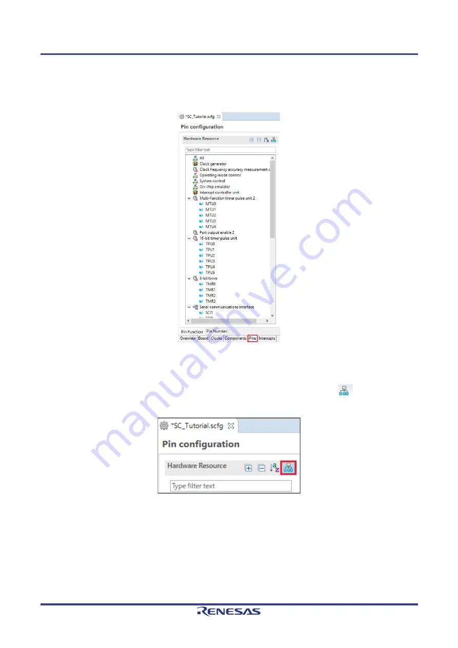
Smart Configurator assigns pins to the software components that are added to the project. Assignment of the 

pins can be changed using the Pins page. 


Figure 4-40  The ‘Pins’ tabbed page 

 
4.6.1 

Change pin assignment of a software component 

 
To change the pin assignment of a software component in the Pin Function list, click 

 to change view to 

show by Software Components. 


Figure 4-41  Change view to show by Hardware Resource 


Содержание RSSK

Страница 1: ... Electronics Corp without notice Please review the latest information published by Renesas Electronics Corp through various means including the Renesas Electronics Corp website http www renesas com RX23W Group Renesas Solution Starter Kit for RX23W Smart Configurator Tutorial Manual For e2 studio Rev 1 00 Aug 2019 32 RENESAS 32 Bit MCU RX Family RX200 Series 32 www renesas com User s Manual ...

Страница 2: ...ons failure or accident arising out of the use of Renesas Electronics products outside of such specified ranges 7 Although Renesas Electronics endeavors to improve the quality and reliability of Renesas Electronics products semiconductor products have specific characteristics such as the occurrence of failure at a certain rate and malfunctions under certain use conditions Unless designated as a hi...

Страница 3: ...put signal during power off state as described in your product documentation 4 Handling of unused pins Handle unused pins in accordance with the directions given under handling of unused pins in the manual The input pins of CMOS products are generally in the high impedance state In operation with an unused pin in the open circuit state extra electromagnetic noise is induced in the vicinity of the ...

Страница 4: ...sensitive equipment Its use outside the laboratory classroom study area or similar such area invalidates conformity with the protection requirements of the Electromagnetic Compatibility Directive and could lead to prosecution The product generates uses and can radiate radio frequency energy and may cause harmful interference to radio communications However there is no guarantee that interference w...

Страница 5: ...sion history summarizes the locations of revisions and additions It does not list all revisions Refer to the text of the manual for details The following documents apply to the RX23W Group Make sure to refer to the latest versions of these documents The newest versions of the documents listed may be obtained from the Renesas Electronics Web site Document Type Description Document Title Document No...

Страница 6: ...ode LSB Least Significant Bit LVD Low Voltage Detect MCU Micro controller Unit MSB Most Significant Bit PC Personal Computer PLL Phase locked Loop Pmod This is a Digilent Pmod Compatible connector Pmod is registered to Digilent Inc Digilent Pmod_Interface_Specification RAM Random Access Memory ROM Read Only Memory RSSK Renesas Solution Starter Kit RTC Real Time Clock SCI Serial Communications Inte...

Страница 7: ...r 18 4 5 3 Interrupt Controller 21 4 5 4 Ports 23 4 5 5 SCI SCIF Asynchronous Mode 27 4 5 6 SPI Clock Synchronous Mode 30 4 5 7 Single Scan Mode S12AD 33 4 6 The Pins tabbed page 36 4 6 1 Change pin assignment of a software component 36 4 7 Building the Project 39 5 User Code Integration 40 5 1 Project Settings 40 5 2 LCD Code Integration 41 5 2 1 SPI Code 43 5 2 2 CMT Code 44 5 3 Additional inclu...

Страница 8: ...io IDE Smart Configurator plug in to create a working project for the RSSK platform 1 2 Features This RSSK provides an evaluation of the following features Project Creation with e2 studio Code generation using the Smart Configurator plug in User circuitry such as switches LEDs and a potentiometer The RSSK board contains all the circuitry required for microcontroller operation ...

Страница 9: ...with custom code Building the project in e2 studio The project generator will create a tutorial project with two selectable build configurations HardwareDebug is a project built with the debugger support included Optimisation is set to zero Release is a project with optimised compile options level two and Outputs debugging information option not selected producing code suitable for release in a pr...

Страница 10: ... C project for the RX23W MCU ready to generate peripheral driver code using Smart Configurator This project generation step is necessary to create the MCU specific source project and debug files 3 2 Creating the Project Start e2 studio and select a suitable location for the project workspace In the Welcome page click Create a new C C project In the Templates for New C C Project dialog selecting Re...

Страница 11: ...he Select toolchain device debug settings dialog select the options as shown in the screenshot opposite In Toolchains choose Renesas CCRX The R5F523W8AxBL MCU is found under RX200 RX23W RX23W 85 pin Select E2 Lite RX from the pulldown and check Create Release Configuration check box Click Next In the Select Coding Assistant Tool dialog select Smart Configurator Click Next ...

Страница 12: ... Click Next A summary dialog will appear click Finish to complete the project generation Wait for file generation to start In future to skip the pop up message on the right check the Always use this setting check box and click on Open Perspective The perspective changes automatically when the Smart Configurator starts up ...

Страница 13: ... if after adding custom code the user needs to re visit Smart Configurator to change any MCU operating parameters Note If code is added outside the above user code area it will be lost if code generation is executed again with Smart Configurator By following the steps detailed in this Tutorial the user will generate an e2 studio project called SC_Tutorial The fully completed Tutorial project is co...

Страница 14: ... to the RX Smart Configurator User s Guide e2 studio You can download the latest document from https www renesas com smart configurator The Smart Configurator initial view is displayed as illustrated in Figure 4 1 Figure 4 1 Overview page Smart Configurator provides GUI features for configuration of MCU sub systems Once the user has configured all required MCU sub systems and peripherals the user ...

Страница 15: ... 64 Aug 30 19 4 3 The Board tabbed page On the Board tabbed page set the board type and device type Click the Board tab and it will be displayed as shown in Figure 4 2 Figure 4 2 Board configuration page 4 3 1 Board configuration page Make sure that Custom User Board is selected for the board Figure 4 3 Select board ...

Страница 16: ...configurations will be reflected in the r_bsp_config h file in src smc_gen r_config 4 4 1 Clocks configuration Figure 4 4 shows a screenshot of Smart Configurator with the Clocks configurations Click on the Clocks tab Configure the system clocks as shown in the figure In the tutorial the HOCO clock is used as the clock source Select the route using the HOCO clock by the selector An exclamation mar...

Страница 17: ...mponents tabbed page 4 5 1 Add a software component into the project Smart Configurator supports five types of software components Startup Drivers Middleware Application and RTOS In the following sub sections the reader is guided through the steps to configure the MCU for a simple project containing interrupts for switch inputs timers ADC and a SCI by component of Drivers Click the Add component i...

Страница 18: ...erval timer for generation of accurate delays CMT1 and CMT2 will be used as timers in de bouncing of switch interrupts Select Compare Match Timer as shown in Figure 4 8 below then click Next Figure 4 8 Select Compare Match Timer In Add new configuration for selected component dialog Resource select CMT0 as shown in Figure 4 9 below then click Finish Figure 4 9 Select Resource CMT0 ...

Страница 19: ...cation Figure 4 10 Config_CMT0 setting Click the Add component icon In Software Component Selection dialog Type select Drivers Select Compare Match Timer then click Next In Add new configuration for selected component dialog Resource select CMT1 as shown in Figure 4 11 below then click Finish Figure 4 11 Select Resource CMT1 Navigate to the Config_CMT1 and configure CMT1 as shown in Figure 4 12 Th...

Страница 20: ...ch Timer then click Next In Add new configuration for selected component dialog Resource select CMT2 as shown in Figure 4 13 below then click Finish Figure 4 13 Select Resource CMT2 Navigate to the Config_CMT2 and configure CMT2 as shown in Figure 4 14 This timer is configured to generate a high priority interrupt after 200ms This timer is used as our long switch de bounce timer later in this tuto...

Страница 21: ...nnected to IRQ1 P31 and SW2 is connected to IRQ0 P30 Click Add component icon In Software Component Selection dialog Type select Drivers Select Interrupt Controller as shown in Figure 4 15 then click Next Figure 4 15 Select Interrupt Controller In Add new configuration for selected component dialog Resource select ICU as shown in Figure 4 16 below then click Finish Figure 4 16 Select Resource ICU ...

Страница 22: ...3W 4 Smart Configurator Using the e2 studio R20UT4449EG0100 Rev 1 00 Page 22 of 64 Aug 30 19 Navigate to the Config_ICU configure these two interrupts as falling edge triggered as shown in Figure 4 17 below Figure 4 17 Config_ICU setting ...

Страница 23: ...nected to P43 and LED3 is connected to P44 PE3 is used as one of the LCD control lines together with PB3 P03 and PJ3 Click Add component icon In Software Component Selection dialog Type select Drivers Select Ports as shown in Figure 4 18 then click Next Figure 4 18 Select Ports In Add new configuration for selected component dialog Resource select PORT as shown in Figure 4 19 below then click Fini...

Страница 24: ... PORTJ as shown in Figure 4 20 below Figure 4 20 Select Port selection Navigate through each of the PORTx tabs configuring these four I O lines and LCD control lines as shown in Figure 4 21 Figure 4 22 Figure 4 23 Figure 4 24 and Figure 4 25 below Ensure that the Output 1 tick box is checked except for PJ3 under the PORTJ tab Start with the PORT0 tab Figure 4 21 Select PORT0 tab ...

Страница 25: ...olution Starter Kit for RX23W 4 Smart Configurator Using the e2 studio R20UT4449EG0100 Rev 1 00 Page 25 of 64 Aug 30 19 Select PORT4 tab Figure 4 22 Select PORT4 tab Select PORTB tab Figure 4 23 Select PORTB tab ...

Страница 26: ...olution Starter Kit for RX23W 4 Smart Configurator Using the e2 studio R20UT4449EG0100 Rev 1 00 Page 26 of 64 Aug 30 19 Select PORTE tab Figure 4 24 Select PORTE tab Select PORTJ tab Figure 4 25 Select PORTJ tab ...

Страница 27: ...provide a USB virtual COM port as shown in the schematic Click Add component icon In Software Component Selection dialog Type select Drivers Select SCI SCIF Asynchronous Mode as shown in Figure 4 26 then click Next Figure 4 26 Select SCI SCIF Asynchronous Mode In Add new configuration for selected component dialog Work mode select Transmission Reception as shown in Figure 4 27 below Figure 4 27 Se...

Страница 28: ...4449EG0100 Rev 1 00 Page 28 of 64 Aug 30 19 In Resource select SCI8 as shown in Figure 4 28 below Figure 4 28 Select Resource SCI8 Ensure that the Configuration name updates to Config_SCI8 as shown in Figure 4 29 below then click Finish Figure 4 29 Ensure Configuration name Config_SCI8 ...

Страница 29: ...udio R20UT4449EG0100 Rev 1 00 Page 29 of 64 Aug 30 19 Configure SCI8 as shown in Figure 4 30 Ensure the Start bit edge detection is set as Falling edge on RXD8 pin and the Bit rate is set to 19200 bps All other settings remain at their defaults Figure 4 30 Config_SCI8 setting ...

Страница 30: ...D on the PMOD2 connector as shown in the schematic Click Add component icon In Software Component Selection dialog Type select Drivers Select SPI Clock Synchronous Mode as shown in Figure 4 31 then click Next Figure 4 31 Select SPI Clock Synchronous Mode In Add new configuration for selected component dialog Operation select Master transmit only as shown in Figure 4 32 below Figure 4 32 Select Ope...

Страница 31: ...49EG0100 Rev 1 00 Page 31 of 64 Aug 30 19 In Resource select SCI12 as shown in Figure 4 33 below Figure 4 33 Select Resource SCI12 Ensure that the Configuration name updates to Config_SCI12 as shown in Figure 4 34 below then click Finish Figure 4 34 Ensure Configuration name Config_SCI12 ...

Страница 32: ... the e2 studio R20UT4449EG0100 Rev 1 00 Page 32 of 64 Aug 30 19 Configure SCI12 as shown in Figure 4 35 Ensure the Transfer direction is set as MSB first and the Bit rate is set to 6000 kbps All other settings remain at their defaults Figure 4 35 Config_SCI12 setting ...

Страница 33: ...ut which is connected to the RV1 potentiometer output on the RSSK Click Add component icon In Software Component Selection dialog Type select Drivers Select Single Scan Mode S12AD as shown in Figure 4 36 then click Next Figure 4 36 Select Single Scan Mode S12AD In Add new configuration for selected component dialog Resource select S12AD0 as shown in Figure 4 37 below then click Finish Figure 4 37 ...

Страница 34: ...0100 Rev 1 00 Page 34 of 64 Aug 30 19 Configure S12AD0 as shown in Figure 4 38 and Figure 4 39 Ensure the Analog input channel tick box for AN000 is checked and the Start trigger source is set to Software trigger All other settings remain at their defaults Figure 4 38 Config_S12AD0 setting 1 ...

Страница 35: ...Renesas Solution Starter Kit for RX23W 4 Smart Configurator Using the e2 studio R20UT4449EG0100 Rev 1 00 Page 35 of 64 Aug 30 19 Figure 4 39 Config_S12AD0 setting 2 ...

Страница 36: ...ns to the software components that are added to the project Assignment of the pins can be changed using the Pins page Figure 4 40 The Pins tabbed page 4 6 1 Change pin assignment of a software component To change the pin assignment of a software component in the Pin Function list click to change view to show by Software Components Figure 4 41 Change view to show by Hardware Resource ...

Страница 37: ...assignment IRQ0 to P30 IRQ1 to P31 Ensure the Enable tick box of IRQ0 and IRQ1 are checked as shown in Figure 4 42 Figure 4 42 Configure pin assignment Config_ICU Select the Config_SCI8 of Software Components In the Pin Function list Assignment column Ensure the Enable tick box of RXD8 and TXD8 are checked and Assignment column of RXD8 is PC6 and TXD8 is PC7 as shown in Figure 4 43 Figure 4 43 Con...

Страница 38: ... tick box of SCK12 and SMOSI12 are checked and Assignment column of SCK12 is PE0 SMOSI12 is PE1 as shown in Figure 4 44 Figure 4 44 Configure pin assignment Config_SCI12 Select the Config_S12AD0 of software components In the Pin Function list Assignment column Ensure the Enable tick box of AN000 AVCC0 and AVSS0 are checked and Assignment column of AN000 is P40 as shown in Figure 4 45 Figure 4 45 C...

Страница 39: ...n is successful as shown Figure 4 47 below Figure 4 47 Smart Configurator console 4 7 Building the Project The project template created by Smart Configurator can now be built In the Project Explorer pane expand the src folder then smc_gen folder Figure 4 48 Generated folder structure Switch back to the C C perspective using the button on the top right of the e2 studio workspace Select SC_Tutorial ...

Страница 40: ...rticular area of code i e function for insertion of user functions and prototypes global for insertion of user global variable declarations or include for insertion of pre processor include directives User code inserted inside these comment delimiters is protected from being overwritten by Smart Configurator if the user subsequently needs to use Smart Configurator to regenerate any of the Smart Co...

Страница 41: ...rovided with the RSSK Refer to the Tutorial project folder created according to the Quick Start Guide procedure Check that the following files are in the src folder ascii c ascii h r_okaya_lcd c r_okaya_lcd h Copy these files in to the src folder below the workspace These files will be automatically added to the project as shown in Figure 5 1 Figure 5 1 Adding files to the project ...

Страница 42: ...ject Tree expand the src folder and open the file SC_Tutorial c by double clicking on it Add header files near the declaration include r_smc_entry h include r_smc_entry h include r_okaya_lcd h include r_cg_userdefine h Scroll down to the main function and insert the highlighted code as shown below into the beginning of the main function void main void Initialize the debug LCD R_LCD_Init Displays t...

Страница 43: ...enerated here Insert the following code in the transmit end call back function for SCI12 static void r_Config_SCI12_callback_transmitend void Start user code for r_Config_SCI12_callback_transmitend Do not edit comment generated here gs_sci12_txdone TRUE End user code Do not edit comment generated here Now insert the following function in the user code area at the end of the file Start user code fo...

Страница 44: ...here static volatile uint8_t gs_one_ms_delay_complete FALSE End user code Do not edit comment generated here Scroll down to the r_Config_CMT0_cmi0_interrupt function and insert the following line in the user code area static void r_Config_CMT0_cmi0_interrupt void Start user code for r_Config_CMT0_cmi0_interrupt Do not edit comment generated here gs_one_ms_delay_complete TRUE End user code Do not e...

Страница 45: ...d directory path dialog click the Workspace button and in the Folder selection dialog browse to the SC_Tutorial src folder and click OK e2 studio formats the path as shown in Figure 5 3 below Figure 5 3 Adding workspace search path Close the property by clicking the Apply and Close button shown in Figure 5 2 and when the Settings dialog shown in Figure 5 4 is appeared click Yes to finish the setti...

Страница 46: ...g_CMT2 c and Config_CMT2_user c as described in 4 5 2 and 4 5 3 It is necessary to provide additional user code in these files to implement the switch press release detection and de bouncing required by the API functions in r_rssk_switch c 5 4 1 Interrupt Code In the e2 studio Project Tree expand the src smc_gen Config_ICU folder and open the file Config_ICU h by double clicking on it Insert the f...

Страница 47: ..._ICU_IRQSetFallingEdge Description This function sets clears the falling edge trigger for the specified ICU_IRQ Arguments uint8_t irq_no uint8_t set_f_edge 1 if setting falling edge triggered 0 if clearing Return Value None void R_ICU_IRQSetFallingEdge const uint8_t irq_no const uint8_t set_f_edge if 1 set_f_edge ICU IRQCR irq_no BYTE _04_ICU_IRQ_EDGE_FALLING else ICU IRQCR irq_no BYTE uint8_t _04...

Страница 48: ...e bounce Timer Code In the e2 studio Project Tree expand the src smc_gen Config_CMT1 folder and open the Config_CMT1_user c file and insert the following code in the user code area for include near the top of the file Start user code for include Do not edit comment generated here Defines switch callback functions required by interrupt handlers include r_rssk_switch h End user code Do not edit comm...

Страница 49: ...iguring the ADC trigger source on the fly once an SW1 or SW2 press is detected In the e2 studio Project Tree expand the src smc_gen general folder and open the file r_cg_userdefine h Insert the following code the user code area resulting in the code shown below Start user code for function Do not edit comment generated here extern volatile uint8_t g_adc_trigger End user code Do not edit comment ge...

Страница 50: ...S12AD0_Start while 1U uint16_t adc_result Wait for user requested A D conversion flag to be set SW1 or SW2 if TRUE g_adc_trigger Call the function to perform an A D conversion adc_result get_adc Display the result on the LCD lcd_display_adc adc_result Reset the flag g_adc_trigger FALSE else do nothing Then add the definition for the switch call back get_adc and lcd_display_adc functions below the ...

Страница 51: ...dc_result return adc_result End of function get_adc Function Name lcd_display_adc Description Converts adc result to a string and displays it on the LCD panel Argument uint16_t adc result Return value none static void lcd_display_adc const uint16_t adc_result Declare a temporary variable uint8_t a Declare temporary character string char lcd_buffer 11 ADC XXXH Convert ADC result into a character st...

Страница 52: ...rupt void Start user code for r_Config_S12AD0_interrupt Do not edit comment generated here g_adc_complete TRUE End user code Do not edit comment generated here Select Build Project from the Project menu or use the button e2 studio will build the project with no errors The project may now be run using the debugger as described in 6 When any switch is pressed the program will perform an A D conversi...

Страница 53: ...rom PC terminal extern uint8_t g_rx_char End user code Do not edit comment generated here Open the file Config_SCI8_user c Insert the following code in the user area for global near the beginning of the file Start user code for global Do not edit comment generated here Global used to receive a character from the PC terminal uint8_t g_rx_char Flag used locally to detect transmission complete static...

Страница 54: ...uint8_t g_rx_char 1 End user code Do not edit comment generated here At the end of the file in the user code area for adding add the following function definition Function Name R_SCI8_AsyncTransmit Description This function sends SCI8 data and waits for the transmit end flag Arguments tx_buf transfer buffer pointer tx_num buffer size Return Value status MD_OK or MD_ARGERROR MD_STATUS R_SCI8_AsyncT...

Страница 55: ...e to store the A D conversion count for user display static uint8_t gs_adc_count 0 Add the following highlighted code in the main function void main void Initialize the switch module R_SWITCH_Init Set the call back function when SW1 or SW2 is pressed R_SWITCH_SetPressCallback cb_switch_press Initialize the debug LCD R_LCD_Init Displays the application name on the debug LCD R_LCD_Display 0 uint8_t ...

Страница 56: ...0x00F0 4 uart_buffer 15 char a 0x0A a 0x30 a 0x37 a char adc_result 0x000F uart_buffer 16 char a 0x0A a 0x30 a 0x37 Send the string to the UART R_DEBUG_Print uart_buffer End of function uart_display_adc Select Build Project from the Project menu e2 studio will build the project with no errors The project may now be run using the debugger as described in 6 Connect the RSSK USBCN0 port to a USB port...

Страница 57: ... uint16_t adc_result Prototype declaration for uart_display_adc static void uart_display_adc const uint8_t gs_adc_count const uint16_t adc_result Variable to store the A D conversion count for user display static uint8_t gs_adc_count 0 Prototype declaration for led_display_count static void led_display_count const uint8_t count Add the following highlighted code in the main function void main void...

Страница 58: ...lse do nothing Then add the following function definition at the end of the file Function Name led_display_count Description Converts count to binary and displays on 4 LEDS0 3 Argument uint8_t count Return value none static void led_display_count const uint8_t count Set LEDs according to lower nibble of count parameter LED0 uint8_t count 0x01 LED_ON LED_OFF LED1 uint8_t count 0x02 LED_ON LED_OFF L...

Страница 59: ...rations In order to execute the project it is necessary to change the following settings in Renesas GDB Hardware Debugging SC_Tutorial HardwareDebug Debugger Connection Settings Ensure that in Connection Settings tab that the Power Target From The Emulator MAX 200mA is set to Yes and Main Clock Source is set to HOCO For more information on powering the RSSKRX23W please refer to the User s Manual F...

Страница 60: ...in Figure 6 4 will be displayed Figure 6 3 Perspective Switch Dialog Click Remember my decision to skip this dialog later Click Yes to confirm that the debug window perspective will be used The debugger will start up and the code will stop at the Smart Configurator function PowerOn_Reset_PC as shown in Figure 6 5 Figure 6 4 Debugger start up screen For more information on the e2 studio debugger re...

Страница 61: ... Details Please refer to the contact details listed in section 9 of the Quick Start Guide General information on Renesas microcontrollers can be found on the Renesas website at https www renesas com Trademarks All brand or product names used in this manual are trademarks or registered trademarks of their respective companies or organisations Copyright This document may be wholly or partially subje...

Страница 62: ...C 1 REVISION HISTORY RX23W Group Renesas Solution Starter Kit for RX23W Smart Configurator Tutorial Manual For e2 studio Rev Date Description Page Summary 1 00 Aug 30 19 First Edition issued ...

Страница 63: ...RX23W Group Renesas Solution Starter Kit for RX23W Smart Configurator Tutorial Manual For e2 studio Publication Date Rev 1 00 Aug 30 19 Published by Renesas Electronics Corporation ...

Страница 64: ...R20UT4449EG0100 RX23W Group ...

Отзывы: