RL78/G1G Sensorless Speed control of 120-degree conducting controlled permanent magnetic synchronous motor (Implementation)
R01AN3582EJ0100 Rev.1.00
Page 18 of 46
Jan 13, 2017
3.1.5 State transition
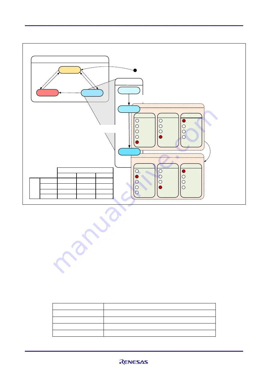
shows state transition diagrams of sensorless 120-degree conducting control software.
SYSTEM MODE
INACTIVE
ERROR
POWER ON/
RESET
[RESET EVENT]
[ACTIVE EVENT]
[INACTIVE EVENT]
[ERROR EVENT]
RUN MODE
INIT
BOOT
Configuration
Control
Curre nt
Spe ed
Po s iti o n
Torq ue
V ol tage
Method
FO C
18 0
WI DE
12 0
Sensor
Less
H all
En co de r
Re s ol ver
Configuration
Control
Curre nt
Spe ed
Po s iti o n
Torq ue
V ol tage
Method
Sensor
Less
H all
En co de r
Re sol ver
DRIVE
ACTIVE
[MTR_DRAW_IN_FINISH ==
g_u1_state_draw_in
]
[MTR_VOFF_SET_STATUS_FINISH ==
g_u1_state_v_offset]
[ERROR EVENT]
[RESET EVENT]
FO C
18 0
WI DE
12 0
INACTIVE
ACTIVE
ERROR
RESET
SYSTEM MODE
INACTIVE
ACTIVE
ERROR
INACTIVE
INACTIVE
INACTIVE
ACTIVE
ERROR
ERROR
ERROR
ERROR
ERROR
INACTIVE
ACTIVE
ERROR
[MTR_V_PI_OUTPUT
== g_u2_state_voltage_ref
]
EVENT
Figure 3-5 State Transition Diagram of Sensorless 120-degree Conducting Control Software
(1) SYSTEM MODE
“SYSTEM MODE” indicates the operating states of the system. The state transits on occurrence of each event
(EVENT). “SYSTEM MODE” has 3 states that are motor drive stop (INACTIVE), motor drive (ACTIVE), and
abnormal condition (ERROR).
(2) RUN MODE
“RUN MODE” indicates the condition of the motor control.
“RUN MODE” transits sequentially as shown in Figure
3-5 when “SYSTEM MODE” is “ACTIVE”.
(3) EVENT
When “EVENT” occurs in each “SYSTEM MODE”, “SYSTEM MODE” changes as shown table in Figure 3-5, per
that “EVENT”.
Table 3-4 List of EVENT
EVENT name
Occurrence factor
INACTIVE
by user operation
ACTIVE
by user operation
ERROR
when the system detects an error
RESET
by user operation


