background image

R0E530650CFJ30 User’s 

Manual 

5. Connection Procedure 

(See Figure 3)


REJ10J1902-0200  Rev.2.00 


Page 2 of 4 

Apr 16, 2010 


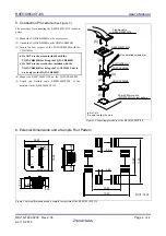
The procedure for connecting the R0E530650CFJ30 is shown 
below. 


(1)  Mount the NQPACK080SB on the user system. 

(2)  Attach the YQPACK080SB on the NQPACK080SB. 

(3) Secure the four corners of the YQPACK080SB with the 

YQ-GUIDEs. 


Do NOT use the screws included with the 

YQPACK080SB for fixing the YQPACK080SB. 


Do NOT use the screwdriver included with the 

NQPACK080SB for fixing the YQ-GUIDEs. That is 

used only for the HQPACK080SB. 

(4) Mount


the R0E530650CFJ30 on the YQPACK080SB. 

(5) Attach the flexible cable R0E001000FLX10 of the 

emulator to the R0E530650CFJ30. 


80-pin 0.65mm pitch
(PLQP0080JA-A) foot pattern

YQPACK080SB

NQPACK080SB

YQ-GUIDE(

×

4)

R0E530650CFJ30

:No.1 pin

Be sure to align the pins.

(1)

(2)

(3)

(4)

(5)

Use a slotted screwdriver.

Flexible cable
R0E001000FLX10


Figure 3 Connection procedure of the R0E530650CFJ30 


6. External Dimensions and a Sample Foot Pattern 


38.00

35.00

16

.50

R0E530650CFJ30

REV.A

CN1

1

50

51

100

CN2

1

50

51

100

MADE IN JAPAN

13

.4

0

17

.2

0

13.40

17.20

0.65

0.35

Unit : mm

6.83

4.08

6.

95

6.95


Figure 4 External dimensions and a sample foot pattern of the R0E530650CFJ30 

Содержание R0E530650CFJ30

Страница 1: ...LQFP Insertion removal iterations of connector 50 times guaranteed 4 Usage See Figure 2 The R0E530650CFJ30 can be used for debugging and on board evaluation in common by mounting the NQPACK080SB on the user system 1 For debugging Mount the NQPACK080SB on the foot pattern of the user system and attach the YQPACK080SB on it In addition connect the R0E530650CFJ30 to the YQPACK080SB and then connect t...

Страница 2: ...Es That is used only for the HQPACK080SB 4 Mount the R0E530650CFJ30 on the YQPACK080SB 5 Attach the flexible cable R0E001000FLX10 of the emulator to the R0E530650CFJ30 80 pin 0 65mm pitch PLQP0080JA A foot pattern YQPACK080SB NQPACK080SB YQ GUIDE 4 R0E530650CFJ30 No 1 pin Be sure to align the pins 1 2 3 4 5 Use a slotted screwdriver Flexible cable R0E001000FLX10 Figure 3 Connection procedure of th...

Страница 3: ...urope This allows you to return equipment to Renesas for disposal through our approved Producer Compliance Scheme To register for the program click here http www renesas com weee 8 Correspondence of Connectors CN1 and CN2 Table 2 Correspondence of the connectors CN1 Pin No IC1 CN1 Pin No IC1 CN2 Pin No IC1 CN2 Pin No IC1 1 100 1 100 2 99 2 99 3 98 3 98 4 97 4 97 5 48 96 47 5 96 6 49 95 46 6 95 7 5...

Страница 4: ... that pose a direct threat to human life 8 You should use the Renesas Electronics products described in this document within the range specified by Renesas Electronics especially with respect to the maximum rating operating supply voltage range movement power voltage range heat radiation characteristics installation and other product characteristics Renesas Electronics shall have no liability for ...

Отзывы: