

PA-5400 Series
docs.paloaltonetworks.com
1
2
Rack Mount the Firewall
The PA-5400 Series firewall ships with a rack mount kit for installation in a four-post 19” equipment rack.
Before You Begin
Use this document to install and begin setting up your Palo Alto Networks PA-5410, PA-5420, or PA-5430 firewall. Refer to the
Firewall Hardware Reference at
https://docs.paloaltonetworks.com/hardware
for safety information, specifications, and more
detailed procedures for installing the firewall.
◼
Verify that the installation site has adequate air circulation and an AC or DC power source.
◼
Ensure that you have both a #1 and #2 Phillips-head torque driver available. Use the #1 Phillips-head bit to attach the rack-mount brackets to
the firewall and use the #2 bit to secure the rack-mount brackets to the equipment rack posts.
◼
Unpack the equipment and verify that you received the following items:
3
Power on the Firewall
The PA-5400 Series firewalls have two AC or DC power supplies for power redundancy.
1
Remove the four nuts from the ground studs located on the back of the appliance on the upper left side.
2
Crimp a 6-AWG wire to the provided grounding lug and connect the other end to your earth ground point.
3
Connect the power supply to a power source based on whether your power supplies are AC or DC.
Page 1 of 2
Quick Start Guide
Ensure that the equipment rack is properly anchored so it can support the weight of the installed equipment.
Connect the second power cord through a different circuit breaker to provide power redundancy and to allow for electrical circuit
maintenance.
1
Attach one fixed rack mount bracket to each side (left and right when facing the front panel) of the firewall. Use four #8-32 x 5/16” screws for
the front four screw holes of each bracket and three #6-32 x 5/16” screws for the three back screw holes of each bracket (Figure 1) and torque
each screw to 15 in-lbs.
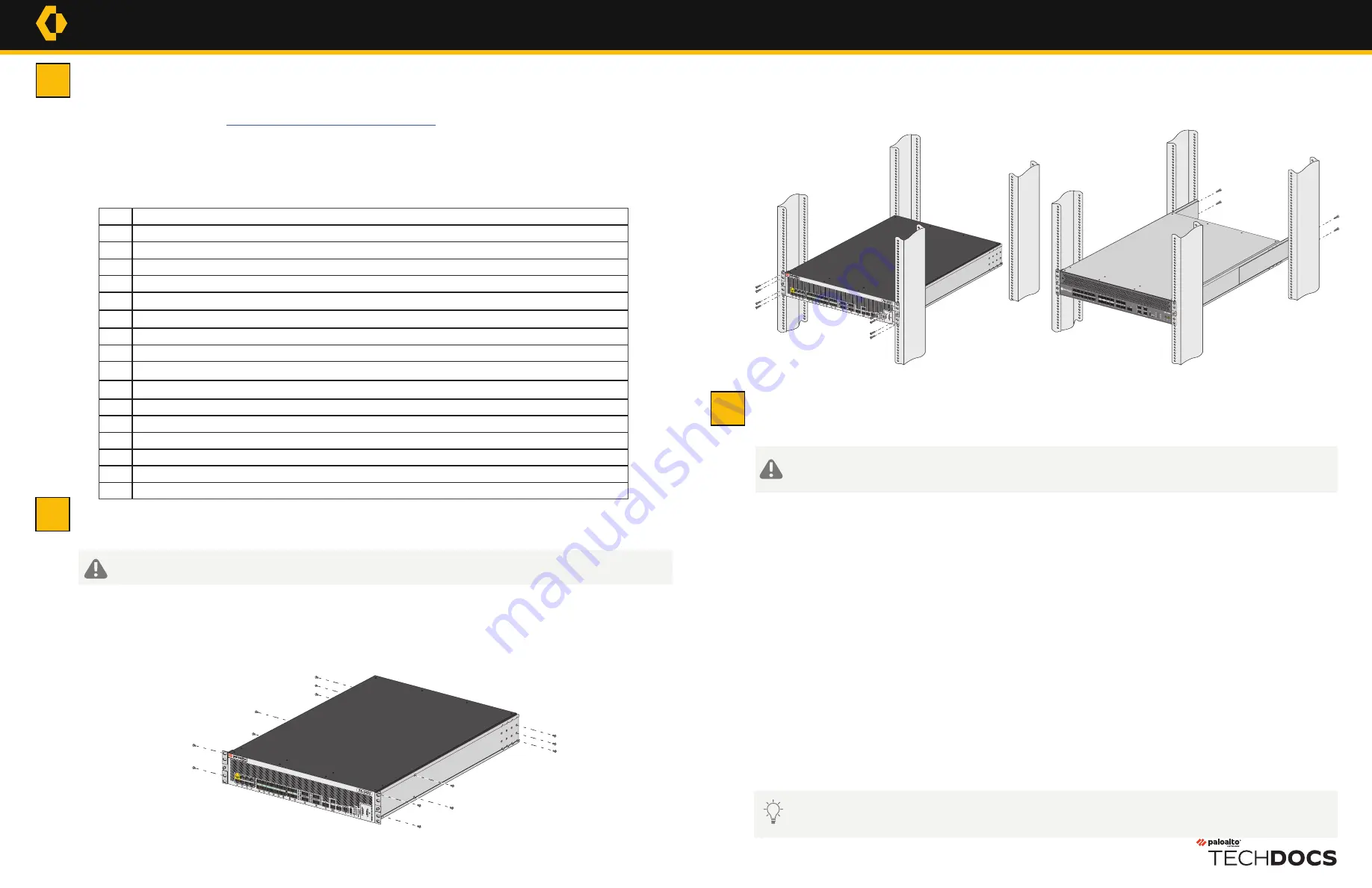
2
With help from another person, hold the firewall in the rack and secure the fixed rack mount brackets to the front rack posts using four screws
for each rail (Figure 2). Use the appropriate screws (#10-32 x 3/4” or #12-24 x 1/2”) for your rack and torque each screw to 25 in-lbs. Use cage
nuts to secure the screws if the rack has square holes.
Figure 1
Figure 2
If you are booting the firewall in non-ZTP mode (Standard mode), follow the instructions in Step 4: Connect to the Management
Interface before proceeding to power on the firewall.
Qty
Description
1
PA-5400 Series next-generation firewall.
2
AC power cords.
2
Velcro straps to secure the AC power cords to the power supplies.
1
Standard Type-A USB to micro USB console cable.
1
Standard RJ-45 CAT6 Ethernet cable for management (MGT) port access.
2
1G SFP transceivers.
2
Fixed rack mount brackets.
2
Adjustable rack mount brackets.
6
#6-32 x 5/16” rack-mount brack screws.
8
#8-32 x 5/16” rack-mount bracket screws.
8
#10-32 x 3/4” rack-mount screws.
8
#12-24 x 1/2” rack-mount screws.
8
#10-32 cage nuts.
1
End User License Agreement (EULA).
1
Limited Warranty document.
1
China Restriction of Hazardous Substances (RoHS) declaration.
3
Slide one adjustable rack mount bracket into each of the two previously installed fixed rack mount brackets. Secure the back brackets to the
back rack posts using four screws for each bracket (#10-32 x 3/4” or #12-24 x 1/2” screws), and torque each screw to 25 in-lbs (Figure 3).
Figure 3
AC Power Supplies
1
Connect the first two power supplies to a 120VAC 15-amp circuit breaker or 240VAC 20-amp circuit breaker using the provided power
cords and then connect the second two power supplies to a second, independent 120VAC 15-amp circuit breaker or 240VAC 20-amp
circuit breaker.
2
Secure the power cords to the power inlets using the provided velcro straps.
DC Power Supplies
1
Prepare the DC power cable (not included) by crimping the bare wire ends of the cables using lugs (not included) designed for your
DC power source. Each cable dongle has one red wire and one black wire. Connect the red wire to the DC negative (-48VDC) terminal
of your DC power source. Connect the black wire to the DC positive (RTN) terminal of your DC power source. Do this for each of the
four power supplies, ensuring that the first two power supplies on the left are connected to one power circuit breaker and the second
pair on the right is connected to a different circuit breaker. This ensures power redundancy and allows for planned electrical circuit
maintenance.
2
Connect the other ends of the DC cables to the front of the DC power supplies by pushing the plastic connector into the DC power
supply until it clicks into place. Ensure that you connect each pair of power supplies to a different circuit breaker.
3
After each AC or DC cable is securely connected, turn on the power source and the appliance will power on.
#8-32 x 5/16”
Screws
#6-32 x 5/16”
Screws


