14
REMKO VRS EN Series
A room thermostat or a day/night
temperature control is connected
to the corresponding terminal
block X2 in the control box for
these versions.
The connection must be made as
follows:
Remove the factory cable bridge
and connect the terminals with
the corresponding wires of
the respective control system.
The respective separate
connection diagrams of the
control system and the unit must
be observed!
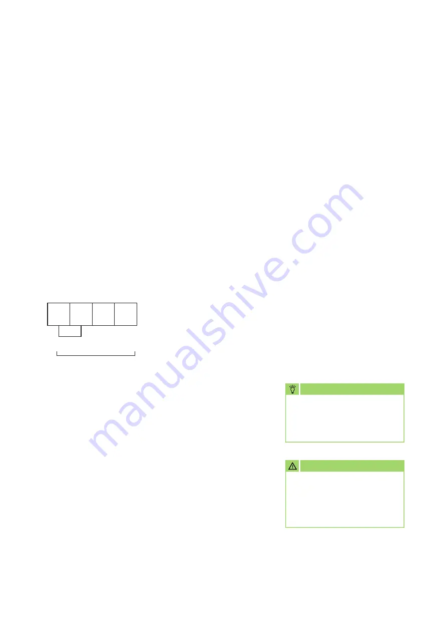
Terminal block
X2
■
The combustion chamber must
not be underloaded (increased
condensate formation)
■
The separate operating
instructions for the burner must
be observed
■
The usability of the forced-air
burner for the unit must be
ensured (WLE version)
Gas connection
Adequate gas pressure and
quantity of gas, in accordance
with unit performance, must be
continuously available during unit
operation.
■
Installation of the gas
connection should be performed
only by authorised specialists
■
The DVGW Code of Practice G
600 for gas-fired fan-assisted
heaters and the TRF for liquid
gas must be observed
■
Gas pressure regulators and
shut-off valves must be
provided by the customer as a
matter of principle
■
The cross-section of
the pipework should be
determined in accordance
with the connection value of
the unit, the total pipework
resistance and the amount of
gas supply pressure
NOTE
Before initial commissioning,
the gas supply line must
be thoroughly cleaned and
checked for leaks!
Heating oil connection
Sufficient and professional fuel
supply must be ensured.
■
The suction pipe in the heating
oil tank must be fitted with
a foot valve as a matter of
principle
■
Even at low outside
temperatures it is necessary
to ensure that there is an
adequate supply of heating oil
that is capable of flowing.
Depending on the quality
of the heating oil, paraffin
formation can start from
approx. 5°C.
Appropriate measures must be
taken to avoid this!
Burner installation
The forced-air burner is mounted
on the front of the unit with a
clamping flange.
Observe the following points:
■
Only type-tested forced-air oil
burners per DIN EN 267 in WLE
design or forced-air gas burners
(per DIN EN 676) may be used
■
It is essential to set the burner
to the full heat load of the unit
CAUTION
Assembly, set-up and
maintenance work on the gas
supply may only be carried out
by specialist personnel authorised
by the gas supply company!
X2 12 13 N PE
2
3
1
PE
RT (optional)
RT (optional)


