12
Prior to Initial Operation
After the impermeability check has been performed, the
vacuum pump must be connected to the valve connec-
tions of the outdoor part by means of the manometer
station and a vacuum created.
Prior to initial operation of the unit and after contact with
the cold cycle, the following checks must be performed
and documented in the initial operation log:
◊
Check all refrigerant lines and valves for leaks with a
leak locator spray or soapy water.
The unit must be shut down.
◊
Check the connection lines to ensure that suction
and injection lines have not been reversed.
◊
Check the refrigerant lines and insulation for dam-
age.
◊
Check the electrical connection between the indoor
unit and the outdoor part for the correct polarity.
◊
Check all fixtures and suspended parts to ensure
that they are in the proper position and at the correct
height.
G
If the refrigerant line is longer than 5 m, more re-
frigerant should be added to the system.
Proceed as follows to add additional refrigerant:
1. Remove the vacuum pump and connect the filling
cylinder.
2. Place the open cylinder on a scale and calibrate the
scale to zero.
3. Create a vacuum in the hose at the height of the ma-
nometer distribution pipe.
4. Use the table above to determine the quantity to add.
5. Open the suction pressure side of the manometer.
6. Close the manometer valve when the appropriate
amount has been added.
Adding Refrigerant
The refrigerant required for operating the system is lo-
cated in the outdoor part.
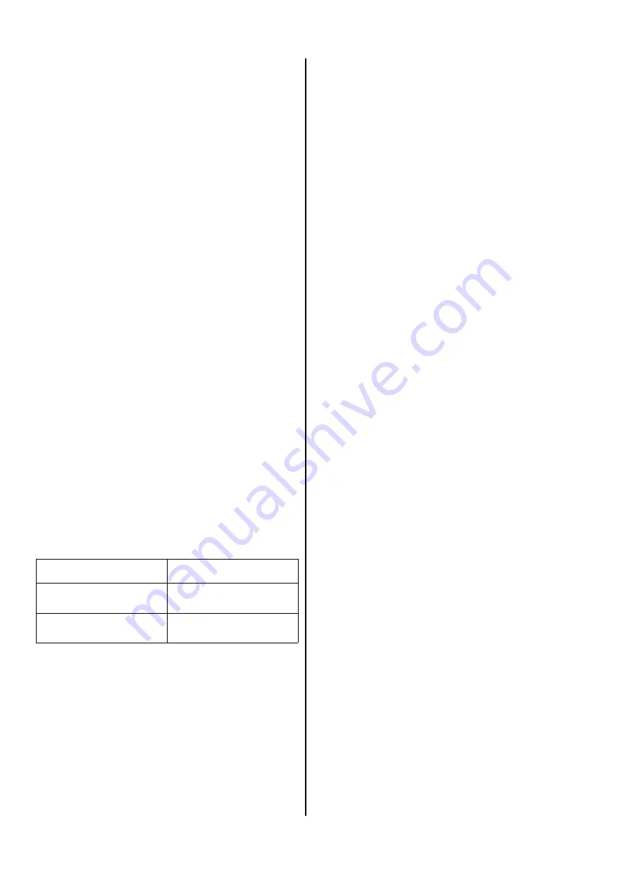
For refrigerant lines longer than 5 m per cycle, refriger-
ant must be added using the following table:
Length of line
Amount per meter
Up to and including 5 m
5 m to max. 15 m
–––
30 g/m
Initial Operation
Initial operation of the unit must comply with the certifi-
cation specifications and must be documented.
Prior to handover
After all components have been connected and
checked, the system can be put into operation.
To ensure that the unit is functioning properly, a func-
tional check must be performed to identify any irregulari-
ties during unit operation before the unit is handed over
to the operator.
This check is dependent on the installed indoor unit.
These procedures are documented in the operating in-
structions of the indoor unit in use
Functional check and test run
The functional checks are started via the indoor unit.
The indoor unit runs in standard cooling operation for
the test.
The following must be checked:
◊
Check refrigerant lines for leaks.
◊
Check that the ventilator and compressor are run-
ning smoothly.
◊
Check that cold air is being expelled from the indoor
unit and warm air from the outdoor part.
◊
Conduct a functional test of the indoor unit and all
program processes.
◊
Check the surface temperature of the suction line
and determine the evaporator overheating.
To measure the temperature, hold the thermometer
on the suction line and subtract the boiling point tem-
perature recorded on the manometer from the meas-
ured temperature.
◊
Document the measured temperatures in the initial
operation log.
Proceed with the test run as follows:
1. Remove the caps from the valves.
2. To begin initial operation, briefly open the shut-off
valves until the manometer displays pressure meas-
uring approx. 2 bar.
3. Check the impermeability of all established connec-
tions with a leak locator spray or suitable devices.
4. If you did not find any leaks, open the shut-off
valves by turning them all the way counter-
clockwise with a hexagonal spanner.
If you found leaks, the connection must be re-
established. It is absolutely necessary to create a
new vacuum and dry the unit!
5. Turn the main switch or the fuse on.
6. Adjust the target temperature on the indoor unit to a
lower value than the existing room temperature us-
ing the remote control.
7. Switch the indoor unit to cooling mode.
Содержание RKS 510
Страница 2: ......


