4
Electrical wiring
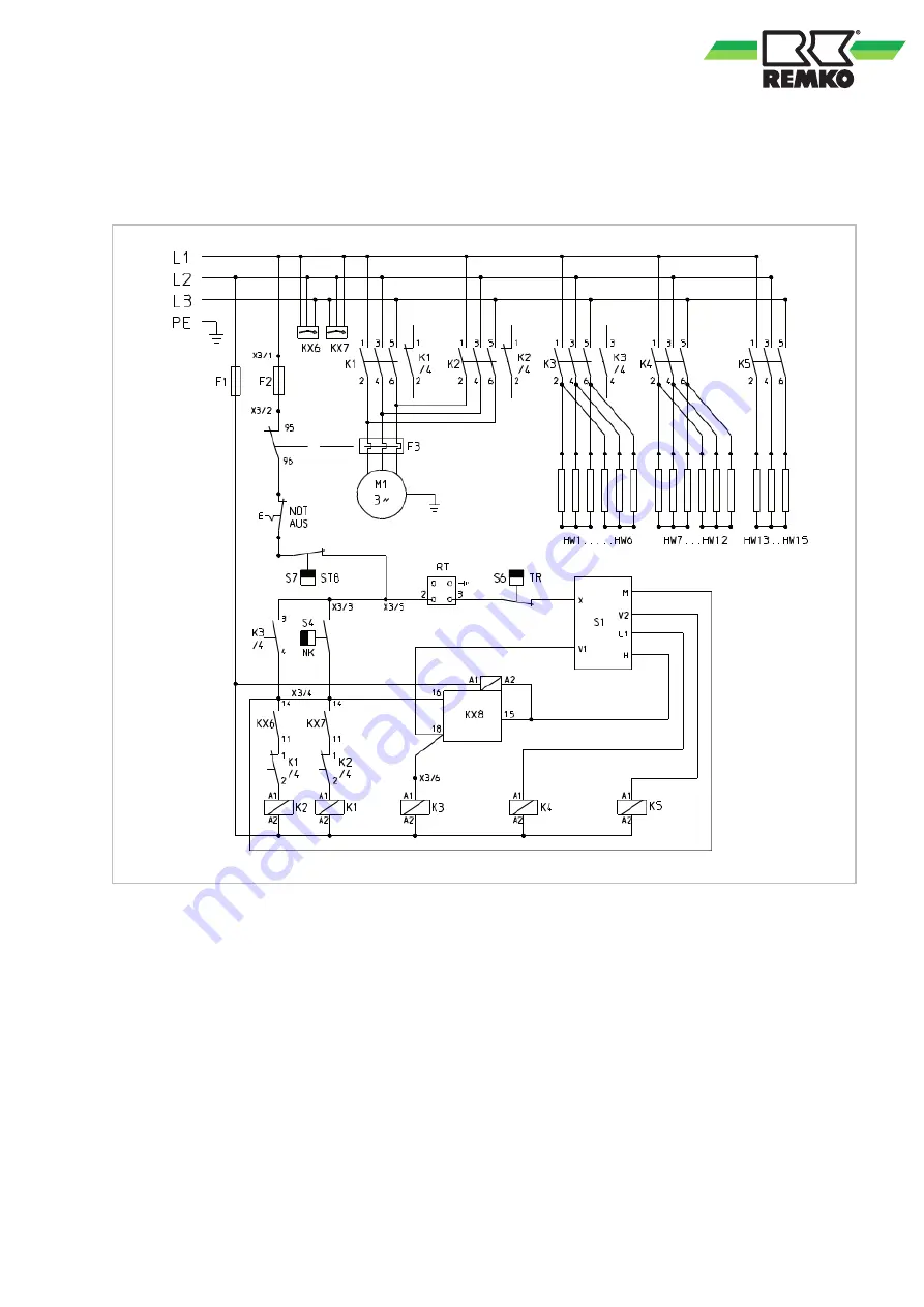
4.1 Electrical wiring diagram
Fig. 1: Electrical wiring diagram
F1:
Control fuse 1
F2:
Control fuse 2
F3:
Motor overload protection switch
HW:
Heating resistor
K1:
Motor protection 1
K2:
Motor protection 2
K3-K5: Contactor for heating stages
KX6:
Phase sequence relay 1
KX7:
Phase sequence relay 2
KX8:
Time relay
M1:
Fan motor
RT:
Room thermostat socket
S1:
Operating switch
S4:
Aftercooler thermostat (NK)
S6:
Temperature controller (TR)
S7:
Safety temperature limiter (STB)
X3/..:
Terminal block
We reserve the right to modify the dimensions and design as part of the ongoing technical development
process.
9
Содержание ELT 40
Страница 19: ......


