


24
Chapter 8
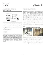
AUTOMATIC
SWITCH
B I L G E
PUMP
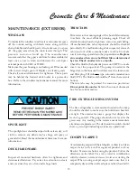
CHECK GRATING
FOR DEBRIS
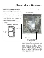
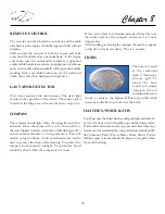
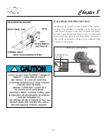
Look for foreign materials in the strainer area or discharge
hose and remove as necessary. Inspect all clamps and
electrical connections for tightness. A quick check of
the bilge pump automatic float switch is afforded by
lifting up on the float located in the sump and listening
for the pump operation.
BILGE PUMP/AUTOMATIC
FLOAT SWITCH
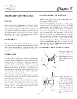
F U E L
VENT
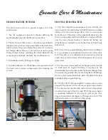
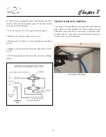
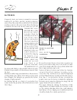
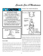
FUEL TANK & FITTINGS
Periodically inspect the fuel tank components for loose
clamps at the vent, fill and feed locations. Examine each
hose for signs of deterioration and leakage. Check the
fuel sender for loose bolts, nuts, and leaks at all areas of
contact. Also, inspect the fuel tank for signs of leakage or
abrasion. Tighten all components as needed.
Never remove the spring and ball assembly in the anti-
siphon valve. It can be cleaned with compressed air. Should
the component be faulty (normally a fuel surge problem
at mid to high speed ranges) contact a marine professional
to replace it. Check the fuel fill pipe hose connection at
the deck using the access plate which can be removed for
inspection. Make sure the black ground wire is tightly
secured. For further information, contact your closest Regal
dealer.
BLOWER
Check the blower hoses to ensure they are fastened in the
bilge properly and there are no holes in them. The hose
connected to the blower needs to be 3/4 the way down in
the bilge to evacuate fumes properly. Ensure there are no
hose traps that can hold water. All vents need to be checked
for debris. Make sure the blower motor is securely fastened
and all hose clamps, tie wraps and electrical connections
are tight.
GRD. BLOCK
HOSE CLAMPS
F U E L
SENDER
ANTI-SIPHON
VALVE
TYPICAL FUEL TANK
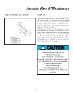
TYPICAL FUEL TANK FITTINGS
FUEL FILL
FUEL SENDER
VENT
ANTI-SIPHON
VALVES
GENERATOR
ENGINES
FUEL FEEDS
Note: Select later fuel systems distributed domestically
include EPA components. This system uses a different
configuration on fuel tanks and fuel distribution hardware
to comply with EPA legislation dated July, 2012.
Therefore the parts in the EPA fuel system may vary in
function and appearance from earlier fuel systems.
Содержание 30 EXPRESS
Страница 1: ...30 EXPRESS OWNER S MANUAL...
Страница 2: ...784022 OWNER S MANUAL 30 EXPRESS 12 2012...
Страница 30: ...11 Safety On Board NAVIGATION LIGHT RULES...
Страница 41: ...Chapter 2 22 Notes...
Страница 44: ...3 Rules Of The Road NAVIGATION RULES...
Страница 85: ...28 Chapter 5 Notes...
Страница 105: ...4 Chapter 7...
Страница 106: ...5 Equipment Operation...
Страница 107: ...6 Chapter 7...
Страница 108: ...7 Equipment Operation...
Страница 109: ...8 Chapter 7...
Страница 110: ...9 Equipment Operation...
Страница 111: ...10 Chapter 7...
Страница 117: ...16 Chapter 7...
Страница 126: ...25 Equipment Operation ROTARY ENCODER AND MENU KEY...
Страница 127: ...26 Chapter 7 USING THE ROTARY ENCODER AND MENU KEY...
Страница 158: ...57 Equipment Operation BACKING A TRAILER 1 2 3 4 LAUNCHING RAMP...
Страница 161: ...60 Chapter 7 Notes...
Страница 195: ...34 Chapter 8 Notes...
Страница 204: ...9 Troubleshooting TOILET SYSTEM DIAGNOSTIC CHART...
Страница 209: ...14 Chapter 9...
Страница 219: ...6 Chapter 11 Notes...
Страница 221: ...2 Chapter 12...
Страница 224: ...5 Technical Information 30 Express Deck Overview 30 Express Cabin Overview...
Страница 225: ...Technical Information 12 6 30 EXPRESS...
Страница 226: ...12 7 Technical Information 30 EXPRESS...
Страница 227: ...Technical Information 12 8 30 EXPRESS...
Страница 228: ...12 9 Technical Information 30 EXPRESS...
Страница 229: ...Technical Information 12 10 30 EXPRESS 30 EXPRESS...
Страница 230: ...12 11 Technical Information TYPICAL NEGATIVE GROUND SYSTEM...
Страница 231: ...Technical Information 12 12 30 EXPRESS...
Страница 232: ...12 13 Technical Information 30 EXPRESS...
Страница 233: ...Technical Information 30 EXPRESS 12 14...
Страница 234: ...12 15 Technical Information 30 EXPRESS...