CE Spring Driven Cord Reels
Page 2
www.reelcraft.com
Installation Instructions
Mounting
CAUTION:
Unless reel was specified differ-
ently when ordering, maximum installation
height is 16 feet. Do not exceed this distance.
Ensure that only a qualified electrician installs/
services this equipment. Installation of GFCI
cord reels should be performed by a qualified
and licensed professional in accordance with
building codes and applicable NEC standards.
1. Unpack and inspect reel for damage. Turn
by hand to check for smooth operation.
Check for completeness.
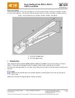
2. Configure reel for top, side or bottom-
wind (bottom-wind for constant tension
reels only) electrical cord dispensing by
removing bolts (1), securing guide arm
bracket (2). Determine new guide arm
location and remove corresponding bolts.
Position guide arm bracket to reel and
replace bolts.
3. Position reel on floor, wall, or ceiling.
Secure into place, using four (customer
supplied) screws or bolts (3).
Installing the Input Electrical Cable
WARNING:
Use only 2.5mm or better cable
for input wiring. Ensure that application does
not exceed electrical rating of reel (refer to
page 1 of this manual). All cord reels with
GFCI receptacles must be hard wired into the
electrical circuit. Use of 2 or 3 prong plugs
may cause a potential malfunction of the GFCI
receptacle.
1. Feed input cable (1) through elbow (2)
and main shaft. Make sure that input
cable extends 150 mm from collector.
2. Screw elbow (2) into reel.
3. Connect input wires (3) and collector
ring wires (4) together using wire nuts
(5). Reference label in slip ring cover for
connections.
4. Take the provided zip tie (not pictured)
and zip tie the input cable wires together
closest to the slip ring.
5. Assemble cover (6) to reel.
Installing the Output
Electrical Cable
WARNING:
Select output cable in accordance
with power requirement of apparatus to be
supplied. Ensure that application does not
exceed electrical rating of reel (refer to page
1 of this manual). Use extreme caution, reel
under tension. Avoid releasing latch mecha-
nism.
1. Manually turn sheave (1) until spring is
tight, back off 2 turns, and latch.
2. Remove access cover (2).
3. Remove 150 mm of output cable jacket(3)
and add fork terminals(4) to ends.
4. Route cable through strain relief (6), then
through cut out in spool (7).
5. Pull enough cable through for roughly
1/2 an inner wrap as shown in the dia-
gram.
6. Connect output wires to terminal block
(8) as shown. Reference label in slip ring
cover for connections.
7. Connect ground wire to grounding stud
(9) as shown.
8. Using Ohmmeter check for ground faults.
9. Take provided cable clamp (not pictured)
and attach it to the wire. Then take the
cable clamp and screw it down to the
brush assembly on the reel.
10. Replace cover (2).
11. Release latch and wind cable onto reel.
12. Install bumper stop (10).
Adjustments - Spring Tension
If necessary, adjust spring tension on reel by
adding or removing wraps of electrical cord
from spool, one wrap at a time, until desired
tension is obtained. Add wraps to increase
tension. Remove wraps to decrease tension.
WARNING:
When adding wraps of electrical
cord, be careful not to exceed the winding
mechanism’s spring capacity. Add just enough
wraps of cord to achieve the desired tension.
Damage to the winding mechanism will result
if spring is over-tensioned. Always be aware
of spring tension on reel. Exercise extreme
caution.
Installing Plugs
Install only CE conforming plug and coupling
rated to a minimum of 16 amps per manufac-
turer’s instructions before applying mains volt-
age. Do not install a male plug at each end.
Troubleshooting Instructions
Troubleshooting of the reel consists of isolat-
ing a problem to a defective electrical cord/
work device, brush holder/brushes, or col-
lector assembly. Refer any other discrepan-
cies only to an authorized service person or
directly to Reelcraft.
WARNING:
The following procedure directs
the technician to take voltage measurements.
Remember, even low voltage is dangerous and
can cause personal injury or death. Exercise
extreme caution! Ensure that only a qualified
electrician installs/services this equipment.
1. If work device is either an incandescent
or fluorescent light, replace bulb with a
known good bulb. If this does not correct
the problem, proceed to step 2. If work
device is an electrical receptacle, ensure
that tool or fixture connected to it is in
good working order. If it is, proceed to
step 2.
1
2
3
4
5
6
2
1
5
3
9
4
8
7
6
10
1
2
1
2
3