


4
Mechanical Hot Tapping Machine
Operator’s Manual
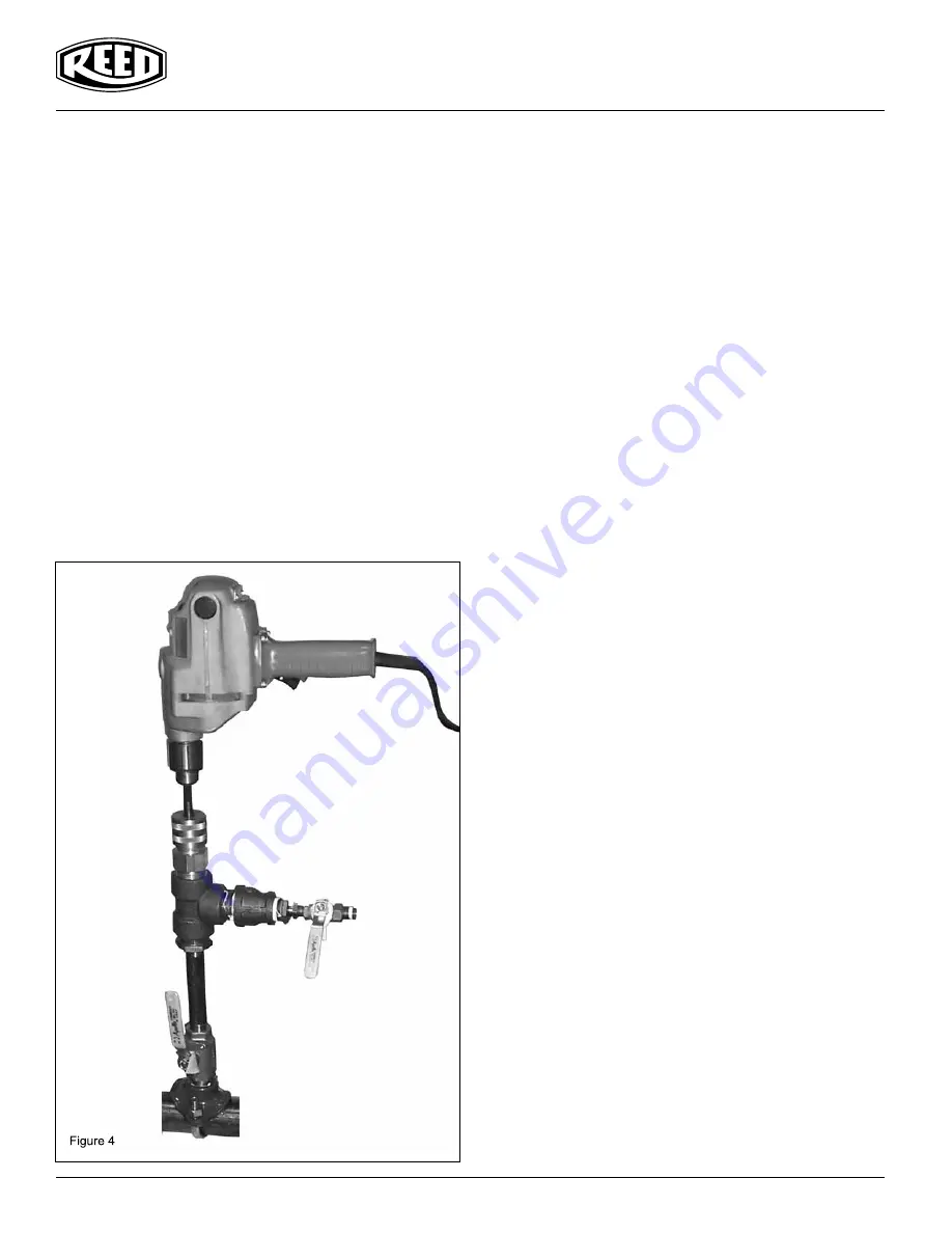
Operation (Using a flanged valve):
Verify all equipment is in good condition. Use only fittings, nipples
and valves pressure rated for the job. Electrical tools and exten-
sion cords must comply with OSHA rules. Using a ground fault
interrupter increases operator safety when using electric power
tools around water and other fluids.
1. Fabricate and weld a pipe saddle and flange assembly
no longer than 4 1/2” from the high part of the mainline
to the face of the flange onto the main.
2. Select the proper size hole saw. Verify the hole saw
clears the gate valve bore adequately. Inadequate
clearance can result in damage should the hole saw
contact the valve while sawing.
3. Bolt the valve to the flange.
4. Select the appropriate shaft.
A. For 5/8” and 1 1/8” hole saws, screw directly to the the
18” shaft (no arbor).
B. For 1 3/8” to 3 1/4” hole saws, use the #43514 arbor
on the 24” shaft.
5. Install Hole Saw.
A. 5/8” to 1 1/8” Hole Saws screw directly to the 18” shaft
B. 1 3/8” to 3 1/4” Hole Saw - insert #43514 arbor into the
24” shaft, tighten set screws. Screw the hole saw on to
the end of the arbor, align barrel pins with holes on hole
saw and turn the upper diameter of the arbor to engage
barrel
pins.
6. Install coupon retaining drill bit. The end of the wire must
extend past the end of the hole saw to retain the coupon.
Align the flats on the bit with the set screw and tighten.
See Figure 5 to set coupon retaining drill bit.
7. A. Apply a thin layer of H1 grease to the shaft before and
after
use.
B. Loosen the Gland Nut and install the shaft gently. Use a
twisting motion while pushing the shaft past the seal in
the Main Body.
C. Tighten the gland nut until snug.
8. Assemble appropriate bleed-off “T” to the Main Body.
9. Assemble the Branch size threaded flange, Branch size
by 1 1/4” bushing, 1 1/4” by close nipple, 1 1/4” by
1 1/ 4” by 1 1/4” “T”, Sealing Unit. See Figure 6.
10. Bolt the Boring Assembly onto the valve.
11. Install the Bleed-off Valve onto the “T”.
12. Pressure test setup through the Bleed-off Valve.
13. Attach hose to Bleed-off Valve for flushing chips to
drain (if desired).
14. Chuck shaft into drill motor.
• MAKE SURE drill is set in non-hammer mode.
• DO NOT USE impact type drills.
15. Drill until pilot drill penetrates the main line. Verify
seals OK. One can hand tighten the Gland Nut should
fluid leak past the Main Body at the shaft. Do not over
tighten the Gland Nut.
16. Resume drilling. Use moderate pressure until the hole
saw penetrates the main completely. Reduce the pressure
on the drill prior to break through. Reducing the pressure
before break through reduces the likelihood of the retainer,
coupon and hole saw hitting the back side of the main.
17. Pull the drill and shaft back to the limit, shut the Branch
Valve, open the Bleed Valve and then disconnect the
Boring Assembly from the Branch valve.
18. Loosen the Gland Nut and remove the one shaft with a
twisting motion. Apply a thin layer of H1 grease to the shaft
to prevent rusting.