background image

2

WARNING DECAL PLACEMENT . . . . . . . . . . . . . . . . . . . . . . . . . . . . . . . . . . . . . . . . . . . . . . . . . . . . . . . . . . . . . . .2

IMPORTANT PRECAUTIONS . . . . . . . . . . . . . . . . . . . . . . . . . . . . . . . . . . . . . . . . . . . . . . . . . . . . . . . . . . . . . . . . . .3

BEFORE YOU BEGIN. . . . . . . . . . . . . . . . . . . . . . . . . . . . . . . . . . . . . . . . . . . . . . . . . . . . . . . . . . . . . . . . . . . . . . . .5

PART IDENTIFICATION CHART. . . . . . . . . . . . . . . . . . . . . . . . . . . . . . . . . . . . . . . . . . . . . . . . . . . . . . . . . . . . . . . .6

ASSEMBLY . . . . . . . . . . . . . . . . . . . . . . . . . . . . . . . . . . . . . . . . . . . . . . . . . . . . . . . . . . . . . . . . . . . . . . . . . . . . . . . .7

OPERATION AND ADJUSTMENT   . . . . . . . . . . . . . . . . . . . . . . . . . . . . . . . . . . . . . . . . . . . . . . . . . . . . . . . . . . . . .14

HOW TO FOLD AND MOVE THE TREADMILL  . . . . . . . . . . . . . . . . . . . . . . . . . . . . . . . . . . . . . . . . . . . . . . . . . . .22

TROUBLESHOOTING   . . . . . . . . . . . . . . . . . . . . . . . . . . . . . . . . . . . . . . . . . . . . . . . . . . . . . . . . . . . . . . . . . . . . . .23

EXERCISE GUIDELINES  . . . . . . . . . . . . . . . . . . . . . . . . . . . . . . . . . . . . . . . . . . . . . . . . . . . . . . . . . . . . . . . . . . . .26

PART LIST. . . . . . . . . . . . . . . . . . . . . . . . . . . . . . . . . . . . . . . . . . . . . . . . . . . . . . . . . . . . . . . . . . . . . . . . . . . . . . . .27

EXPLODED DRAWING. . . . . . . . . . . . . . . . . . . . . . . . . . . . . . . . . . . . . . . . . . . . . . . . . . . . . . . . . . . . . . . . . . . . . .28

ORDERING REPLACEMENT PARTS. . . . . . . . . . . . . . . . . . . . . . . . . . . . . . . . . . . . . . . . . . . . . . . . . . .  Back Cover

LIMITED WARRANTY. . . . . . . . . . . . . . . . . . . . . . . . . . . . . . . . . . . . . . . . . . . . . . . . . . . . . . . . . . . . . . .  Back Cover

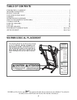
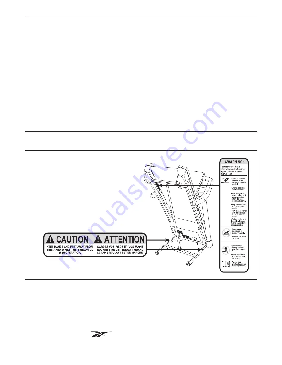
This drawing shows the locations of the warning 

decals. If a decal is missing or illegible, call 

the telephone number on the front cover of 

this manual and request a free replacement 

decal. Apply the decal in the location shown. 

Note: The decals may not be shown at actual 

size.

WARNING DECAL PLACEMENT

256836

TABLE OF CONTENTS

REEBOK and the Vector Logo             are registered trademarks and service marks of Reebok. This product is 

manufactured and distributed under license from Reebok International.

Содержание Competitor Rt 6.0 Treadmill

Страница 1: ...9212 0 Serial No Write the serial number in the space above for reference QUESTIONS If you have questions or if parts are damaged or missing PLEASE CONTACT OUR CUSTOMER SERVICE DEPARTMENT DIRECTLY CALL TOLL FREE 1 888 936 4266 Mon Fri 7 30 until 16 30 ET excluding holidays OR E MAIL US customerservice iconcanada ca www reebokfitness com Serial Number Decal ...

Страница 2: ...ANTY Back Cover This drawing shows the locations of the warning decals If a decal is missing or illegible call the telephone number on the front cover of this manual and request a free replacement decal Apply the decal in the location shown Note The decals may not be shown at actual size WARNING DECAL PLACEMENT 256836 TABLE OF CONTENTS REEBOK and the Vector Logo are registered trademarks and servi...

Страница 3: ... included and plug the surge suppres sor into an appropriate outlet see page 14 To avoid overloading the circuit do not plug other electrical devices except for low power devices such as cell phone chargers into the surge suppressor or into an outlet on the same circuit 13 Use only a surge suppressor that meets all of the specifications described on page 14 To purchase a surge suppressor call the ...

Страница 4: ...l 23 When folding or moving the treadmill make sure that the storage latch is holding the frame securely in the storage position 24 Do not change the incline of the treadmill by placing objects under the treadmill 25 Never insert any object into any opening on the treadmill 26 Inspect and properly tighten all parts of the treadmill regularly 27 DANGER Always unplug the power cord immediately after...

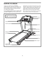
Страница 5: ...ront cover of this manual To help us assist you note the product model number and serial number before contacting us The model number and the location of the serial number decal are shown on the front cover of this manual Before reading further please familiarize yourself with the parts that are labeled in the drawing below BEFORE YOU BEGIN Length 5 ft 10 in 178 cm Width 2 ft 10 in 86 cm Handrail ...

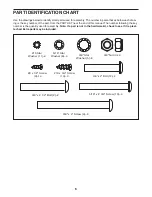
Страница 6: ...r the end of this manual The number following the key number is the quantity used for assembly Note If a part is not in the hardware kit check to see if it is preat tached Extra parts may be included 3 8 x 2 Bolt 12 2 10 Star Washer 11 4 3 8 x 2 1 2 Bolt 2 2 3 8 x 4 Screw 4 6 5 16 x 2 3 4 Screw 10 4 5 16 Star Washer 8 4 3 8 Star Washer 5 6 3 8 Nut 3 4 8 x 1 2 Screw 9 14 10 x 3 4 Screw 13 4 ...

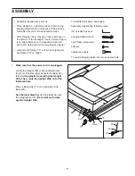
Страница 7: ...identify small parts see page 6 Assembly requires the following tools the included hex keys one adjustable wrench one Phillips screwdriver scissors needlenose pliers To avoid damaging parts do not use power tools ASSEMBLY 1 Make sure that the power cord is unplugged Locate the Upright Wire 70 bundled around the front of the Base 80 beneath the Belly Pan 68 Cut the plastic tie securing the Upright ...

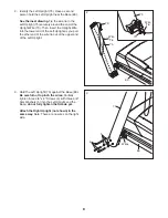
Страница 8: ...t Upright as you pull the other end of the wire tie out of the upper end of the Left Upright 2 70 75 75 Wire Tie 70 Wire Tie 3 Hold the Left Upright 75 against the Base 80 Be careful not to pinch the wires Partially tighten three 3 8 x 4 Screws 4 with three 3 8 Star Washers 5 into the Left Upright and the Base do not fully tighten the Screws yet Attach the Right Upright not shown in the same way N...

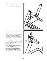
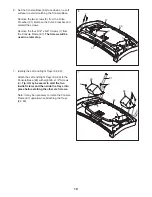
Страница 9: ...the wire tie on the Upright Wire 70 into the bottom and out of the end of the left Handrail 71 as shown Then pull the Upright Wire through the left Handrail Attach the left handrail assembly A to the Left Upright 75 with two 5 16 x 2 3 4 Screws 10 and two 5 16 Star Washers 8 Make sure not to pinch the Upright Wire 70 Do not tighten the Screws yet Remove and discard the two indicated screws B from ...

Страница 10: ... 7 from the Console Frame 87 The Screws will be used in a later step 87 83 93 92 87 9 9 7 7 Identify the Left and Right Trays 92 93 Attach the Left and Right Trays 92 93 to the Console Base 83 with eight 8 x 1 2 Screws 9 Tip It may be easier to start the two inside Screws and then slide the Trays into place before starting the other six Screws Note It may be necessary to rotate the Console Frame 8...

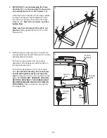
Страница 11: ...ith the help of a second person hold the con sole assembly near the left Handrail 71 and the right Handrail not shown Connect the ground wire from the console assembly to the Console Ground Wire 89 on the Pulse Crossbar 31 Connect the Upright Wire 70 to the console wire See the inset drawing The connectors should slide together easily and snap into place If they do not turn one connector and try a...

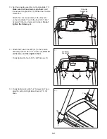
Страница 12: ...ur 5 16 x 5 8 Screws 7 that you removed in step 6 Do not tighten the Screws yet 10 71 Console Assembly 7 7 70 71 87 11 Attach the Pulse Crossbar 31 to the console assembly with six 8 x 1 2 Screws 9 Start all six Screws and then tighten them Firmly tighten the four 5 16 x 5 8 Screws 7 12 Firmly tighten all six 3 8 x 4 Screws 4 Then slide the Left and Right Base Covers 73 74 down 11 12 31 Console As...

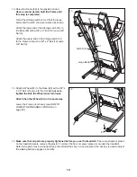
Страница 13: ...that the large barrel and the latch knob are oriented as shown Attach the lower end of the Storage Latch 51 to the Base 80 with a 3 8 x 2 Bolt 12 and a 3 8 Nut 3 Attach the upper end of the Storage Latch 51 to the Frame 49 with a 3 8 x 2 Bolt 12 and a 3 8 Nut 3 15 Make sure that all parts are properly tightened before you use the treadmill If there are sheets of plastic on the treadmill decals rem...

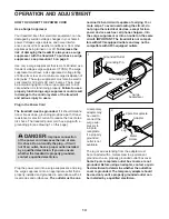
Страница 14: ...d into a surge suppressor and plug the surge suppressor into an appropriate outlet that is properly installed and grounded in accordance with all local codes and ordinances The outlet must be on a nominal 120 volt circuit capable of carrying 15 or more amps To avoid overloading the circuit do not plug other electrical devices except for low power devices such as cell phone chargers into the surge ...

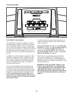
Страница 15: ...iFit cards are available sepa rately To purchase iFit cards at any time go to www iFit com or call the telephone number on the front cover of this manual iFit cards are also avail able at select stores You can even listen to your favorite workout music or audio books with the console s stereo sound system while you exercise To turn on the power see page 16 To use the man ual mode see page 16 To us...

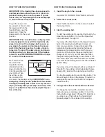
Страница 16: ... THE MANUAL MODE 1 Insert the key into the console See HOW TO TURN ON THE POWER at the left 2 Select the manual mode Press the Manual button on the console to select the manual mode 3 Start the walking belt To start the walking belt press the Start button the Speed increase button or one of the Speed but tons numbered 1 through 10 If you press the Start button or the Speed increase button the walk...

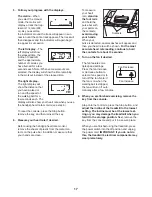
Страница 17: ...from the metal con tacts on the pulse bar In addition make sure that your hands are clean To measure your heart rate stand on the foot rails and hold the pulse bar with your palms on the contacts avoid moving your hands When your pulse is detected several dashes will appear and then your heart rate will be shown For the most accurate heart rate reading continue to hold the contacts for about 15 se...

Страница 18: ...dicates the speed setting for the current segment At the end of each segment a series of tones will sound If a new speed and or incline setting is programmed for the next segment the new speed and or incline setting will flash in the displays for a few seconds The treadmill will automatically adjust to the new speed and or incline setting The workout will continue in this way until the last segmen...

Страница 19: ...cline setting are programmed for each segment Note The same speed and or incline setting may be programmed for consecutive segments 3 Start the walking belt The weight loss workout will function in the same way as a distance workout see step 3 on page 18 4 Follow your progress with the displays See step 5 on page 17 Note The calorie goal is an estimate of the number of calories that you will burn ...

Страница 20: ... Start button or the Speed increase but ton to start the workout A moment after you press the button the treadmill will automatically adjust to the first speed and incline settings of the workout Hold the handrails and begin walking During the workout the voice of a personal trainer will guide you through the workout If the speed or incline setting for the current segment is too high or too low yo...

Страница 21: ...ou remove the key the displays will remain lit although the buttons will not function If the demo mode is turned on a d will appear in the left display while the information mode is selected To turn on or turn off the demo mode press the Speed decrease button An E for English miles or an M for metric kilome ters will appear in the right display Press the Speed increase button to change the unit of...

Страница 22: ...in the storage position Moving the treadmill may require two people 1 Hold the frame and one of the handrails and place one foot against a wheel 2 Pull back on the handrail until the treadmill will roll on the wheels and carefully move it to the desired location CAUTION Do not move the tread mill without tipping it back do not pull on the frame and do not move the treadmill over an uneven surface ...

Страница 23: ...off during use a Check the power switch see the drawing above If the switch has tripped wait for five minutes and then press the switch back in b Make sure that the power cord is plugged in If the power cord is plugged in unplug it wait for five minutes and then plug it back in c Remove the key from the console and then reinsert it d If the treadmill still will not run please see the front cover o...

Страница 24: ...se or decrease button again When the incline is calibrated remove the key from the console SYMPTOM The walking belt slows when walked on a Use only a surge suppressor that meets all of the specifications described on page 14 b If the walking belt is overtightened treadmill per formance may decrease and the walking belt may become damaged Remove the key and UNPLUG THE POWER CORD Using the hex key t...

Страница 25: ...n plug in the power cord insert the key and run the treadmill for a few minutes Repeat until the walking belt is centered b If the walking belt slips when walked on first remove the key and UNPLUG THE POWER CORD Using the hex key turn both idler roller screws clockwise 1 4 of a turn When the walk ing belt is correctly tightened you should be able to lift each edge of the walking belt 2 to 3 in 5 t...

Страница 26: ...ic Exercise If your goal is to strengthen your cardiovascular system you must perform aerobic exercise which is activity that requires large amounts of oxygen for prolonged periods of time For aerobic exercise adjust the intensity of your exercise until your heart rate is near the highest number in your training zone WORKOUT GUIDELINES Warming Up Start with 5 to 10 minutes of stretch ing and light...

Страница 27: ...gnet 45 1 Reed Switch Clamp 46 1 Drive Motor Belt 47 1 Drive Motor 48 2 Frame Spacer 49 1 Frame 50 1 Right Foot Rail 51 1 Storage Latch 52 1 Right Rear Foot 53 1 Left Rear Foot 54 1 Reed Switch 55 4 8 x 1 Screw 56 1 Idler Roller 57 1 Motor Hood 58 2 Incline Frame Spacer 59 1 Incline Frame 60 1 Incline Motor 61 1 Controller Ground Wire 62 1 Controller 63 3 Wire Tie 64 1 Belly Pan Plate 65 1 Power S...

Страница 28: ...38 39 50 49 14 37 27 23 47 26 42 28 26 28 14 26 3 25 40 43 44 12 46 48 48 19 45 30 30 30 30 30 12 1 16 16 56 54 26 19 52 53 19 19 32 36 19 32 32 32 19 19 3 30 30 30 30 30 36 36 36 34 EXPLODED DRAWING A Model No RCTL69212 0 R0912A ...

Страница 29: ...29 9 1 67 65 61 63 62 1 58 59 58 18 20 21 60 22 6 57 6 64 21 21 17 17 20 21 18 6 6 6 6 68 6 6 66 18 6 6 6 18 18 EXPLODED DRAWING B Model No RCTL69212 0 R0912A ...

Страница 30: ... 15 77 15 78 77 2 81 3 33 3 2 81 33 67 79 79 77 77 33 79 35 33 79 35 70 73 4 5 76 5 4 4 5 72 88 71 69 84 71 13 13 11 11 10 7 8 10 8 74 29 89 31 9 9 9 9 6 6 75 7 1 EXPLODED DRAWING C Model No RCTL69212 0 R0912A ...

Страница 31: ...31 55 55 90 6 91 90 83 85 9 9 9 92 9 9 9 6 6 6 6 6 6 93 87 86 6 6 82 6 6 6 6 EXPLODED DRAWING D Model No RCTL69212 0 R0912A ...

Страница 32: ...me service the customer will be responsible for a minimal trip charge This warranty does not extend to freight damage to the product This warranty will automatically be voided if the product is used as a store display model if all instructions in this manual are not followed if the prod uct is abused or improperly or abnormally used or if the product is used for commercial or rental purposes No ot...

Отзывы: