16
4.
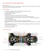
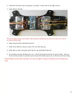
Install ESCs (3m heavy duty mounting tape, also there are zip tie slots on the edge of frame)
5.
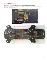
Solder ESCs to FLEX PDB
*
Check resistance between the Positive (red) and Negative (black) wires to make sure they’re not shorted,
resistance should be high.
6.
Solder motors to ESCs (install braid optional)
7.
Check motor direction and swap a wires if it’s incorrectly spinning
8.
Solder battery cable to designated pads near the rear (install braid optional)
9.
Mount Flight Controller with Nylon Hex nuts. Connect Motor Signals from ESC to flight controller. (Only one
Power and Ground wire is required) A servo crimper and 2.54mm jumper pins can be used to shorten cabling
*Please follow the instruction manual for your specific Flight Controller to finish the rest of the electronic
setup
Содержание Strider flex 250
Страница 1: ...1 ...
Страница 2: ...2 ...
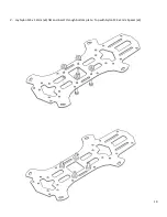
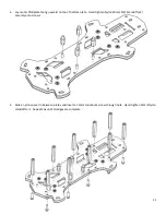
Страница 10: ...10 2 Lay Nylon M3 x 12mm x4 flat and insert through bottom plate Top with Nylon M3 x 3mm Spacer x4 ...
Страница 14: ...14 ...
Страница 19: ...19 ...


