9
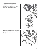
2.4
Install actuator RP940 (
H
)
2.4.1
Install base (
H2
) of actuator into chopper bracket
(E) with
- M8 x 40 fl ange bolt and lock nut (
H1
)
- both sides
2.4.2
Install shaft (
H3
) of actuator into left tailboard
bracket (
C
) with:
- M8 x 65 round head bolt and lock nut (
H4
)
- head of bolt to be on inside of tailboard
- both sides
2.4.3.3
Adjust tailboard hook (
D
) until tailboards are
even when up and to allow some stroke left in the gas
shock (
S
) when the hook stops on the limiter pin (
F
)
124mm - 127mm (4 7/8” - 5”)
2.3
With the tailboad down, on the inside of the hook (
D
)
install limiter pin (
F
) into left chopper wall with:
- M8 x 40 round head bolt (
D1
)
- head of bolt to be on inside of chopper
- fl at washer (D2)
- limiter tube (G)
- lock nut (D3)
- both sides
D
D2
D3
D1
F
G
C
H4
H
H2
E
D
S
F
H1
H3
Tailboards even

