background image

5

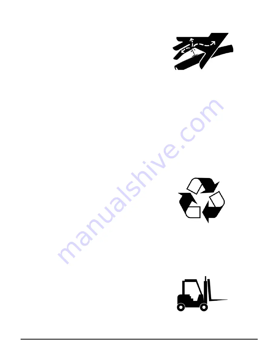
0.11   Avoid High-Pressure Fluids

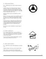
0.11.1   Inspect hydraulic hoses periodically – at least 
once per year – for leakage, kinking, cuts, cracks, 
abrasion, blisters, corrosion, exposed wire braid or any 
other signs of wear or damage.

Replace worn or damaged hose assemblies immediately.

Escaping fl uid under pressure can penetrate the skin 
causing serious injury.

Avoid the hazard by relieving pressure before 
disconnecting hydraulic or other lines. Tighten all 
connections before applying pressure.

Search for leaks with a piece of cardboard. Protect hands 
and body from high-pressure fl uids.

If an accident occurs, see a doctor immediately. Any fl uid 
injected into the skin must be surgically removed within 
a few hours or gangrene may result. Doctors unfamiliar 
with this type of injury should reference a knowledgeable 
medical source. 

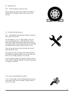
0.12   Dispose of Waste Properly

0.12.1   Improperly disposing of waste can threaten the 
environment and ecology. Potentially harmful waste 
includes such items as oil, fuel, coolant, brake fl uid, 
fi lters, and batteries.

Use leakproof containers when draining fl uids. Do not 
use food or beverage containers that may mislead 
someone into drinking from them.

Do not pour waste onto the ground, down a drain, or into 
any water source.

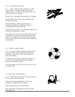
0.13   Use Proper Lifting Equipment

0.13.1   Lifting heavy components incorrectly can cause 
severe injury or machine damage.

Follow recommended procedure for removal and 
installation of components in the manual.

Ensure lifting equipment is rated for the job

Ensure operator is appropriately licensed to operate 
lifting equipment

Содержание Actuated Tailboard

Страница 1: ...1 Actuated Tailboard Installation Manual CS0357 01_V0_Sept 2017 TM ...

Страница 2: ...most serious hazards WARNING or CAUTION safety signs are located near specific hazards or precautionary areas in this manual 0 4 Follow Safety Instructions 0 4 1 Carefully read all safety messages in this manual and on your machine Keep safety signs in good condition Replace missing or damaged safety signs Be sure new equipment components and repair parts include the current safety signs Replacemen...

Страница 3: ...consideration the width of the attachment and the fact that the rear end of the machine swings out Attachments and ground conditions affect the driving characteristics of the combine Never leave machine unattended as long as engine is running 0 6 Work In Ventilated Area 0 6 1 Engine exhaust fumes can cause sickness or death If it is necessary to run an engine in an enclosed area remove the exhaust ...

Страница 4: ... for service work Keep all parts in good condition and properly installed Fix damage immediately Replace worn or broken parts Remove any buildup of grease oil or debris On self propelled equipment disconnect battery ground cable before making adjustments on electrical systems or welding on machine 0 8 Block Wheels 0 8 1 Park the combine on level ground Always engage the park brake and block the co...

Страница 5: ...ved within a few hours or gangrene may result Doctors unfamiliar with this type of injury should reference a knowledgeable medical source 0 12 Dispose of Waste Properly 0 12 1 Improperly disposing of waste can threaten the environment and ecology Potentially harmful waste includes such items as oil fuel coolant brake fluid filters and batteries Use leakproof containers when draining fluids Do not use...

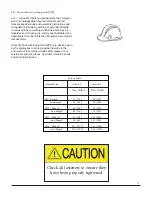
Страница 6: ...pment required for this assembly Personal Protective Equipment PPE are devices worn by the employees to protect against hazards in the environment Examples include safety glasses face shields respirators gloves hard hats steel toe shoes and hearing protection Check all fasteners to ensure they have been properly tightened Torque Table Nominal Size Class 8 8 Class 10 9 Nm ft lbs Nm ft lbs M8 flange...

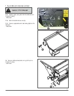
Страница 7: ...g A from the tailboard and chopper housing both sides 1 1 2 Block the tailboard up securely 1 1 3 Remove adjustable latch assembly B from the tailboard both sides 1 2 Remove tailboard adjustment lug C from the chopper housing both sides B C Caution Pinch Hazard A C B ...

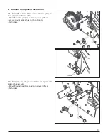
Страница 8: ...h M8 x 25 round head bolts and flange nuts C1 x2 ensure mount bracket has notch on bottom both sides C D C1 Notch 2 2 Install actuator chopper mount bracket E onto left side of chopper with M8 x 20 round head bolts and flange nuts E1 x2 both sides E1 E 2 Actuator Component Installation ...

Страница 9: ... of tailboard both sides 2 4 3 3 Adjust tailboard hook D until tailboards are even when up and to allow some stroke left in the gas shock S when the hook stops on the limiter pin F 124mm 127mm 4 7 8 5 2 3 With the tailboad down on the inside of the hook D install limiter pin F into left chopper wall with M8 x 40 round head bolt D1 head of bolt to be on inside of chopper flat washer D2 limiter tube ...

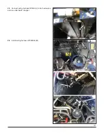
Страница 10: ...10 2 5 Connect wiring harness RP892 J to both actuators and run underneath chopper 2 6 Install wiring harness 47590048 K J K K K K K ...

Страница 11: ... the Machine Configuration for Residue System 3 4 Calibrate the windrow door and spread control actuators following the instructions in the Combine Owner s Manual 3 3 Set configuration to Configuration Name Type ID Value Residue System 0x209C Windrow Door 0x20A1 1 installed Left Spread Deflector 0x2112 1 installed Center Spread Deflector 0x2113 0 not installed Right Spread Deflector 0x2114 1 installed H...

Страница 12: ... full power when everything is running smoothly at lower speeds Check all fasteners to ensure they have been properly tightened When starting chopper be sure all people are clear of the rear of the combine Torque Table Nominal Size Class 8 8 Class 10 9 Nm ft lbs Nm ft lbs M8 flanged 27 20 39 29 non flanged 25 18 35 26 M10 flanged 54 40 57 42 non flanged 49 36 70 51 M12 flanged 93 69 134 98 non fla...

Отзывы: