


Connecting and Routing the Cables
4-14
SmartEdge 100 Router Hardware Guide
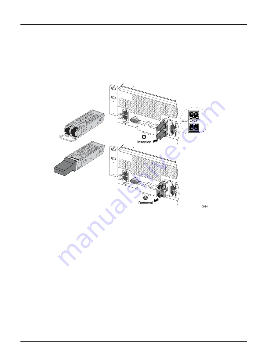
3. With the transceiver aligned with the connector in the chassis front panel or MIC front panel (as shown
in Figure 4-9), slide the transceiver into the opening for the port until the rear connector is seated and
the locking mechanism snaps into place. In Figure 4-9, the SFP is aligned with an upper port, either
native or MIC; to install the SFP in a lower port, rotate the SFP 180°.
4. Leave the dust cover on until you are ready to insert the fiber-optic cables.
Figure 4-9
Installing an SFP Transceiver
Connecting and Routing the Cables
The following sections describe the tasks to connect and route the cables:
•
Connections for Management Access
•
Connect and Route the Cables at the Front of the Chassis
•
Connect the Equipment and Network Ends of the Cables
Appendix A, “Cables and Pin Assignments,” describes SmartEdge 100 cable specifications.
Содержание SmartEdge 100
Страница 4: ......
Страница 8: ...viii SmartEdge 100 Router Hardware Guide...
Страница 14: ...Ordering Documentation xiv SmartEdge 100 Router Hardware Guide...
Страница 52: ...Connecting and Routing the Cables 4 18 SmartEdge 100 Router Hardware Guide...
Страница 72: ...Obtaining Assistance 5 20 SmartEdge 100 Router Hardware Guide...
Страница 90: ...FE and GE MIC and Native Port Cables A 6 SmartEdge 100 Router Hardware Guide...
Страница 94: ...FE and GE Port Alarms B 4 SmartEdge 100 Router Hardware Guide...