7
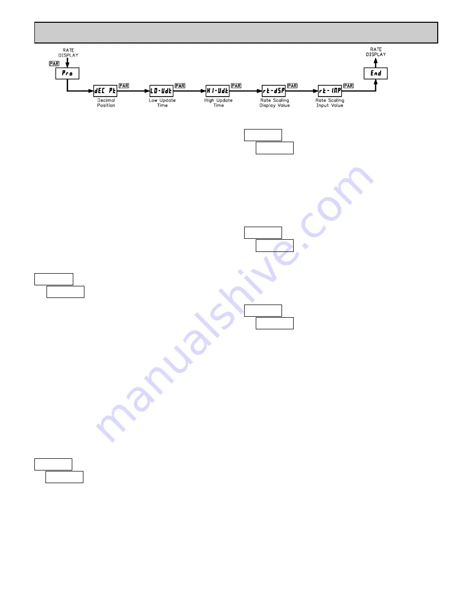
The Rate Indicator has five programmable parameters which are entered in
the sequence shown above, using the front panel push buttons.
Before programming, refer to the section on Scaling the Meter to determine
the Rate Scaling Display Value and Rate Scaling Input Value to use for the
specific application.
Note: Programming mode can be locked out with the Program Disable DIP
switch. With the switch in the Disabled (up) position the meter will not enter
programming mode. Refer to the section on DIP switch setup.
PROGRAMMING MODE ENTRY
Press the
PAR
key to enter Programming Mode. The meter briefly displays
#$%
followed by the first programming parameter described below.
PROGRAMMING PARAMETERS
In programming mode, the display alternates between the parameter and the
current selection or value for that parameter. The dual display with arrows is
used below to illustrate the alternating display. The selection choices or value
range for each parameter is shown to the right of the alternating display.
This parameter selects the decimal point position on the display. The
selection does not affect scaling calculations.
Press the arrow keys (
"
or
!
) to sequence through the selection list until the
desired selection is shown. Press the
PAR
key to save the displayed selection
and advance to the next parameter.
ENTERING NUMERICAL VALUES
The parameters which follow are displayed as a multi-digit numerical values
with one selected digit flashing (initially the far left digit). Press the
"
(up
arrow) key to increment the value of the selected (flashing) digit. Holding the
"
key automatically scrolls the value of the selected digit.
Press the
!
(down arrow) key to select the next digit position to the right.
Use the
"
key to increment the value of this digit to the desired number. Press
the
!
key again to select the next digit to be changed. Holding the
!
key
automatically scrolls through each digit position.
Repeat the “select and set” sequence until all digits are displaying the desired
numerical value. Press the
PAR
key to save the displayed value and advance to
the next parameter.
The Low Update Time is the minimum amount of time between display
updates. The factory setting of 1.0 allows a minimum of one second between
updates. Low values below 0.3 seconds will update the display correctly, but
may cause the display to appear unsteady.
For more details on display updating, refer to Input Frequency Calculation.
The High Update Time is the maximum amount of time before the display is
forced to zero. The High Update Time
must
be higher than the Low Update
Time and also higher than the desired slowest readable speed (one divided by
pulses per second). The factory setting of 2.0 will force the display to zero for
speeds below 0.5 Hz or one pulse every 2 seconds.
For more details on display updating, refer to Input Frequency Calculation.
Enter the desired Rate Display value to be shown for the corresponding Rate
Input value entered below. For more explanation, refer to Rate Scaling.
If a decimal point was selected in the Decimal Position (
&'( #*
) parameter,
it will be displayed at the same position for this parameter value.
Enter the Rate Input value that corresponds to the Rate Display value entered
above. This value is always in pulses per second (Hz). For more explanation,
refer to Rate Scaling.
PROGRAMMING MODE EXIT
The meter exits Programming Mode when the
PAR
key is pressed to save the
Rate Scaling Input Value. The meter briefly displays
'+&
upon exiting
Programming Mode. All programmed selections are now transferred to the non-
volatile memory and the meter returns to the Rate display.
(If power loss occurs during programming mode, verify parameter changes
and reprogram, if necessary, when power is restored.)
PROGRAMMING MODE TIME OUT
The Programming Mode has an automatic time out feature. If no keypad
activity is detected for approximately 60 seconds, the meter automatically exits
Programming Mode. The meter briefly displays
'+&
and returns to the Rate
display. When automatic timeout occurs, any changes that were made to the
parameter currently being programmed, will not be saved.
FACTORY SETTINGS
The factory settings for the programming parameters are shown above in the
alternating display illustrations. The factory settings can be easily restored by
removing power from the meter, and then pressing and holding the
PAR
key
while power is reapplied. The meter displays
$','*
until the
PAR
key is
released. The normal power-up sequence then resumes, with the factory settings
loaded and saved in non-volatile memory.
Note: The Program Disable DIP switch must be in the Enabled (down)
position to allow loading factory settings. See section on DIP switch setup.
"
#
)
&'( #*
"
#
*+)
,-#.$"
)+*
to
00+0
seconds
DECIMAL POSITION
LOW UPDATE TIME (DISPLAY UPDATE)
)+)))))
)+))
)+))))
)+)
)+)))
)
"
#
1+)
2'#.$"
)+1
to
00+0
seconds
HIGH UPDATE TIME (DISPLAY ZERO)
"
#
*)))
!"#$%&
)
to
000000
RATE SCALING DISPLAY VALUE
"
#
*)))+)
!"#'(&
)
to
00000+0
RATE SCALING INPUT VALUE
6.0 P
ROGRAMMING THE
M
ETER
PROGRAMMING SEQUENCE


