background image

56

Chapter 3. Installing and Configuring Red Hat Cluster Suite Software

Unrestricted — Allows you to specify that a subset of members are preferred, but that a

cluster service assigned to this domain can run on any available member.

Restricted — Allows you to restrict the members that can run a particular cluster service.

If none of the members in a restricted failover domain are available, the cluster service

cannot be started (either manually or by the cluster software).

Unordered — When a cluster service is assigned to an unordered failover domain, the

member on which the cluster service runs is chosen from the available failover domain

members with no priority ordering.

Ordered — Allows you to specify a preference order among the members of a failover

domain. The member at the top of the list is the most preferred, followed by the second

member in the list, and so on.

By default, failover domains are unrestricted and unordered.
In a cluster with several members, using a restricted failover domain can minimize the

work to set up the cluster to run a cluster service (such as

httpd

), which requires you to

set up the configuration identically on all members that run the cluster service). Instead of

setting up the entire cluster to run the cluster service, you must set up only the members in

the restricted failover domain that you associate with the cluster service.

Tip

To configure a preferred member, you can create an unrestricted failover domain compris-

ing only one cluster member. Doing that causes a cluster service to run on that cluster

member primarily (the preferred member), but allows the cluster service to fail over to any

of the other members.

The following sections describe adding a failover domain, removing a failover domain, and

removing members from a failover domain:

Section 3.8.1

Adding a Failover Domain

Section 3.8.2

Removing a Failover Domain

Section 3.8.3

Removing a Member from a Failover Domain

3.8.1. Adding a Failover Domain

To add a failover domain, follow these steps:

1. At the left frame of the the

Cluster Configuration Tool

, click

Failover Domains

.

Содержание Cluster Suite

Страница 1: ...Red Hat Cluster Suite Configuring and Managing a Cluster ...

Страница 2: ...t Inc 2000 2003 This material in Part II Configuring a Linux Virtual Server Cluster may be distributed only subject to the terms and conditions set forth in the Open Publication License V1 0 or later the latest version is presently available at http www opencontent org openpub Distribution of substantively modified versions of this material is prohibited without the explicit permission of the copy...

Страница 3: ...Tasks 35 3 2 Overview of the Cluster Configuration Tool 36 3 3 Installing the Red Hat Cluster Suite Packages 39 3 4 Starting the Cluster Configuration Tool 40 3 5 Naming The Cluster 43 3 6 Configuring Fence Devices 44 3 7 Adding and Deleting Members 49 3 8 Configuring a Failover Domain 55 3 9 Adding Cluster Resources 60 3 10 Adding a Cluster Service to the Cluster 62 3 11 Propagating The Configura...

Страница 4: ...figuring Services on the Real Servers 101 9 Setting Up a Red Hat Enterprise Linux LVS Cluster 103 9 1 The NAT LVS Cluster 103 9 2 Putting the Cluster Together 106 9 3 Multi port Services and LVS Clustering 107 9 4 FTP In an LVS Cluster 109 9 5 Saving Network Packet Filter Settings 112 10 Configuring the LVS Routers with Piranha Configuration Tool 115 10 1 Necessary Software 115 10 2 Logging Into t...

Страница 5: ...Index 165 Colophon 171 ...

Страница 6: ......

Страница 7: ... to Part II Configuring a Linux Virtual Server Cluster for more information This guide assumes that the user has an advanced working knowledge of Red Hat Enter prise Linux and understands the concepts of server computing For more information about using Red Hat Enterprise Linux refer to the following resources Red Hat Enterprise Linux Installation Guide for information regarding installation Red H...

Страница 8: ...administration refer to the Red Hat Enterprise Linux System Administra tion Guide For reference information on Red Hat Enterprise Linux refer to the Red Hat Enterprise Linux Reference Guide 2 Document Conventions In this manual certain words are represented in different fonts typefaces sizes and weights This highlighting is systematic different words are represented in the same style to indicate t...

Страница 9: ... graphical session and returns you to the graphical login screen or the console text found on a GUI interface A title word or phrase found on a GUI interface screen or window is shown in this style Text shown in this style indicates that a particular GUI screen or an element on a GUI screen such as text associated with a checkbox or field Example Select the Require Password checkbox if you would l...

Страница 10: ... shown in this style Examples stephen maturin stephen leopard login user input Text that the user types either on the command line or into a text box on a GUI screen is displayed in this style In the following example text is displayed in this style To boot your system into the text based installation program you must type in the text command at the boot prompt replaceable Text used in examples th...

Страница 11: ...o not take effect until you restart the DHCP daemon Caution Do not perform routine tasks as root use a regular user account unless you need to use the root account for system administration tasks Warning Be careful to remove only the necessary partitions Removing other partitions could result in data loss or a corrupted system environment 3 More to Come This manual is part of Red Hat s growing com...

Страница 12: ...ation included in your subscription you must activate your subscription by register ing with Red Hat Registration includes these simple steps Provide a Red Hat login Provide a subscription number Connect your system The first time you boot your installation of Red Hat Enterprise Linux you are prompted to register with Red Hat using the Setup Agent If you follow the prompts during the Setup Agent y...

Страница 13: ...subscription number when prompted during the Setup Agent or by visiting http www redhat com register 4 3 Connect Your System The Red Hat Network Registration Client helps you connect your system so that you can begin to get updates and perform systems management There are three ways to connect 1 During the Setup Agent Check the Send hardware information and Send sys tem package list options when p...

Страница 14: ...viii Introduction ...

Страница 15: ...discusses the installation and con figuration of cluster systems using the recommended hardware and Red Hat Enterprise Linux This section is licensed under the GNU Free Documentation License For details refer to the Copyright page Table of Contents 1 Red Hat Cluster Manager Overview 1 2 Hardware Installation and Operating System Configuration 9 3 Installing and Configuring Red Hat Cluster Suite So...

Страница 16: ......

Страница 17: ... example you can provide clients with access to highly available database applications by building a cluster service using Red Hat Cluster Manager to manage service availability and shared Red Hat GFS storage partitions for the database data and end user applications You can associate a cluster service with a failover domain a subset of cluster nodes that are eligible to run a particular cluster s...

Страница 18: ...r support and multi initiator parallel SCSI configurations are not compatible or appropriate for use as shared cluster storage Cluster configuration and administration framework Red Hat Cluster Manager allows you to easily configure and administer cluster ser vices to make resources such as applications server daemons and shared data highly available To create a cluster service you specify the res...

Страница 19: ...e cluster service as long as that node is active If a cluster service is assigned to an unrestricted failover domain the cluster service starts on any available cluster node if none of the nodes of the failover domain are available Data integrity assurance To ensure data integrity only one node can run a cluster service and access cluster service data at one time The use of power switches in the c...

Страница 20: ...ty In addition to automatic cluster service failover a cluster allows you to cleanly stop cluster services on one node and restart them on another node You can perform planned maintenance on a node system while continuing to provide application and data availability Event logging facility To ensure that problems are detected and resolved before they affect cluster service availability the cluster ...

Страница 21: ...ation files through ccsd ccsd CCS daemon that runs on all cluster nodes and provides configuration file data to cluster software Resource Group Manager rgmanager clusvcadm Command used to manually enable disable relocate and restart user services in a cluster clustat Command used to display the status of the cluster including node membership and services running clurgmgrd Daemon used to handle use...

Страница 22: ... Intelligent Platform Management Interface IPMI fence_manual Fence agent for manual interaction Note Manual fencing is not supported for production environments fence_mcdata Fence agent for McData Fibre Channel switch fence_node Command used by lock_gulmd when a fence operation is required This command takes the name of a node and fences it based on the node s fencing configuration fence_rps10 Fen...

Страница 23: ...hat runs on each node and communicates with all nodes in GFS cluster libgulm so xxx Library for GULM lock manager support gulm_tool Command that configures and debugs the lock_gulmd server LOCK_NOLOCK lock_nolock o Kernel module installed on a node using GFS as a local file system GNBD gnbd o Kernel module that implements the GNBD device driver on clients gnbd_serv o Kernel module that implements ...

Страница 24: ...8 Chapter 1 Red Hat Cluster Manager Overview ...

Страница 25: ...ows administrators to use commodity hardware to set up a cluster configuration that meets the performance availability and data integrity needs of applications and users Cluster hardware ranges from low cost minimum configurations that include only the components required for cluster operation to high end configurations that include redundant Ethernet channels hardware RAID and power switches Rega...

Страница 26: ...ting its services during failover Power switches protect against data corruption in cases where an unresponsive or hung node tries to write data to the disk after its replacement node has taken over its services If you are not using power switches in the cluster cluster service failures can result in services being run on more than one node which can cause data corruption Refer to Section 2 5 2 Co...

Страница 27: ...er with at least two host ports Two HD68 SCSI cables Each cable connects one host bus adapter to one port on the RAID controller creating two single initiator SCSI buses Table 2 1 Example of Minimum Cluster Configuration The minimum hardware configuration is a cost effective cluster configuration for develop ment purposes however it contains components that can cause service outages if failed For ...

Страница 28: ...attached to a Fibre Channel SAN switch For more information about configuring and using Red Hat GFS refer to the Red Hat GFS Adminis trator s Guide Figure 2 1 Hardware Configuration for Improved availability A hardware configuration that ensures data integrity under failure conditions can include the following components At least two servers to run cluster services Switched Ethernet connection bet...

Страница 29: ...a cable to connect to the fence device Two RJ45 to DB9 crossover cables RJ45 to DB9 crossover cables connect a serial port on each node to the Cyclades terminal server Two power switches Power switches enable each node to power cycle the other node before restarting its services Two RJ45 Ethernet cables for a node are connected to each switch FlashDisk RAID Disk Array with dual controllers Dual RA...

Страница 30: ...Basic Cluster Hardware for more information 2 1 2 Choosing the Type of Fence Device The Red Hat Cluster Manager implementation consists of a generic power management layer and a set of device specific modules which accommodate a range of power manage ment types When selecting the appropriate type of fence device to deploy in the cluster it is important to recognize the implications of specific dev...

Страница 31: ...e type of power switch Type Description Models Network attached power switches Remote LAN Internet fencing using RJ45 Ethernet connections and remote terminal access to the device APC MasterSwitch 92xx 96xx WTI NPS 115 NPS 230 IPS 15 IPS 800 IPS 800 CE and TPS 2 Fabric Switches Fence control interface integrated in several models of fabric switches used for Storage Area Networks SANs Used as a way...

Страница 32: ...etwork cable One for each network interface A conventional network cable such as a cable with an RJ45 connector connects each network interface to a network switch or a network hub Yes Table 2 6 Network Hardware Table Hardware Quantity Description Required Host bus adapter One per node To connect to shared disk storage install either a parallel SCSI or a Fibre Channel host bus adapter in a PCI slo...

Страница 33: ...o ensure symmetry of device IDs and LUNs many RAID arrays with dual redundant controllers must be configured in an active passive mode Refer to Appendix A Supplementary Hardware Information for more information Yes SCSI cable One per node SCSI cables with 68 pins connect each host bus adapter to a storage enclosure port Cables have either HD68 or VHDCI connectors Cables vary based on adapter type ...

Страница 34: ...mended for cluster operation Connect the power cables for the shared storage enclosure and both power switches to redundant UPS systems Note that a UPS system must be able to provide voltage for an adequate period of time and should be connected to its own power circuit Strongly rec ommended for availability Table 2 8 UPS System Hardware Table Hardware Quantity Description Required Terminal server...

Страница 35: ...his task After performing the previous tasks install Red Hat Enterprise Linux as described in Sec tion 2 4 Installing and Configuring Red Hat Enterprise Linux 2 3 1 Installing the Basic Cluster Hardware Nodes must provide the CPU processing power and memory required by applications In addition nodes must be able to accommodate the SCSI or Fibre Channel adapters net work interfaces and serial ports...

Страница 36: ...when setting up shared disk storage in a cluster It is recommended to use a clustered file system such as Red Hat GFS to configure Red Hat Cluster Manager storage resources as it offers shared storage that is suited for high availability cluster services For more information about installing and configuring Red Hat GFS refer to the Red Hat GFS Administrator s Guide Whether you are using Red Hat GF...

Страница 37: ...isks and Section 2 5 3 2 Creating File Systems for more information on configuring disks 2 3 3 Setting Up a Console Switch Although a console switch is not required for cluster operation it can be used to facilitate node management and eliminate the need for separate monitors mouses and keyboards for each cluster node There are several types of console switches For example a terminal server enable...

Страница 38: ...local file systems such as etc tmp and var on shared disks or on the same SCSI bus as shared disks This helps prevent the other cluster nodes from accidentally mounting these file systems and also reserves the limited number of SCSI identification numbers on a bus for cluster disks Place tmp and var on different file systems This may improve node perfor mance When a node boots be sure that the nod...

Страница 39: ...ommand to display the devices configured in the kernel Refer to Section 2 4 4 Displaying Devices Configured in the Kernel for more information about performing this task 8 Verify that the nodes can communicate over all the network interfaces by using the ping command to send test packets from one node to another 9 If intending to configure Samba services verify that the required RPM packages for S...

Страница 40: ...n local systems from the local host entry if necessary Note that each network adapter must be configured with the appropriate IP address and netmask The following example shows a portion of the output from the sbin ip addr list command on a cluster node 2 eth0 BROADCAST MULTICAST UP mtu 1356 qdisc pfifo_fast qlen 1000 link ether 00 05 5d 9a d8 91 brd ff ff ff ff ff ff inet 10 11 4 31 22 brd 10 11 ...

Страница 41: ...screens May 22 14 02 10 storage3 kernel scsi0 Adaptec AHA274x 284x 294x EISA VLB PCI Fast SCSI 5 1 28 3 2 4 May 22 14 02 10 storage3 kernel May 22 14 02 10 storage3 kernel scsi1 Adaptec AHA274x 284x 294x EISA VLB PCI Fast SCSI 5 1 28 3 2 4 May 22 14 02 10 storage3 kernel May 22 14 02 10 storage3 kernel scsi 2 hosts May 22 14 02 11 storage3 kernel Vendor SEAGATE Model ST39236LW Rev 0004 May 22 14 0...

Страница 42: ...nel scsi detected 9 SCSI disks total The following example of the dmesg command output shows that a quad Ethernet card was detected on the node May 22 14 02 11 storage3 kernel 3c59x c v0 99H 11 17 98 Donald Becker May 22 14 02 11 storage3 kernel tulip c v0 91g ppc 7 16 99 May 22 14 02 11 storage3 kernel eth0 Digital DS21140 Tulip rev 34 at 0x9800 00 00 BC 11 76 93 IRQ 5 May 22 14 02 12 storage3 ke...

Страница 43: ...s Onboard serial ports ttyS USB devices usb SCSI devices sd 2 5 Setting Up and Connecting the Cluster Hardware After installing Red Hat Enterprise Linux set up the cluster hardware components and verify the installation to ensure that the nodes recognize all the connected devices Note that the exact steps for setting up the hardware depend on the type of configuration Refer to Section 2 1 Choosing...

Страница 44: ...e During the boot up process enter the BIOS utility to modify the node setup as follows Ensure that the SCSI identification number used by the host bus adapter is unique for the SCSI bus it is attached to Refer to Section A 3 4 SCSI Identification Num bers for more information about performing this task Enable or disable the onboard termination for each host bus adapter as required by the storage ...

Страница 45: ...network device if the first device fails link detection To configure two network devices for channel bonding perform the following 1 Create a bonding devices in etc modprobe conf For example alias bond0 bonding options bonding miimon 100 mode 1 This loads the bonding device with the bond0 interface name as well as passes options to the bonding driver to configure it as an active backup master devi...

Страница 46: ...is swapping or has a high system workload For this reason adequate time is allowed prior to concluding that a node has failed If a node fails and a fence device is used in the cluster the fencing daemon power cycles the hung node before restarting its services This causes the hung node to reboot in a clean state and prevent it from issuing I O and corrupting cluster service data When used fence de...

Страница 47: ...PS systems and connect one power switch or one node s power cord if not using power switches and one of the storage subsystem s power cords to each UPS system A redundant UPS system configuration is shown in Figure 2 2 Figure 2 2 Redundant UPS System Configuration An alternative redundant power configuration is to connect the power switches or the nodes power cords and the disk storage subsystem t...

Страница 48: ... raw devices on the partitions Use parted to modify a disk partition table and divide the disk into partitions While in parted use the p to display the partition table and the mkpart command to create new partitions The following example shows how to use parted to create a partition on disk Invoke parted from the shell using the command parted and specifying an available shared disk device At the ...

Страница 49: ... be one of the four primary partitions parted mkpart extended 40 2000 parted p Disk geometry for dev sda 0 000 4340 294 megabytes Disk label type msdos Minor Start End Type Filesystem Flags 1 0 030 21 342 primary 2 21 343 38 417 primary 3 38 417 2001 952 extended An extended partition allows the creation of logical partitionsinside of it The following example shows the division of the extended par...

Страница 50: ...s are powered on and con nected to the shared storage reboot the other node for it to recognize the modifications After partitioning a disk format the partition for use in the cluster For example create the file systems for shared partitions Refer to Section 2 5 3 2 Creating File Systems for more information on configuring file systems For basic information on partitioning hard disks at installati...

Страница 51: ...on 3 9 Adding Cluster Resources Section 3 10 Adding a Cluster Service to the Cluster Section 3 11 Propagating The Configuration File New Cluster Section 3 12 Starting the Cluster Software 3 1 Software Installation and Configuration Tasks Installing and configuring Red Hat Cluster Suite software consists of the following steps 1 Installing Red Hat Cluster Suite software Refer to Section 3 3 Install...

Страница 52: ... to the other nodes in the cluster Refer to Section 3 11 Propagating The Configuration File New Cluster 10 Starting the cluster software Refer to Section 3 12 Starting the Cluster Software 3 2 Overview of the Cluster Configuration Tool The Cluster Configuration Tool Figure 3 1 is a graphical user interface GUI for creating editing saving and propagating the cluster configuration file etc cluster c...

Страница 53: ...on with the following components in the left frame Cluster Nodes Defines cluster nodes Nodes are represented by name as subordinate elements under Cluster Nodes Using configuration buttons at the bottom of the right frame below Properties you can add nodes delete nodes edit node properties and configure fencing methods for each node Fence Devices Defines fence devices Fence devices are represented...

Страница 54: ...properties when a resource is selected Services Use this section to create and configure services that combine cluster resources nodes and failover domains as needed Services are represented as subor dinate elements under Services Using configuration buttons at the bottom of the right frame below Properties you can create services when Services is selected or edit service properties when a service...

Страница 55: ...h node for the Red Hat Cluster Suite and Red Hat GFS products Tip You can access the Red Hat Cluster Suite and Red Hat GFS products by using Red Hat Network to subscribe to and access the channels containing the Red Hat Cluster Suite and Red Hat GFS packages From the Red Hat Network channel you can manage entitlements for your cluster nodes and upgrade packages for each node within the Red Hat Net...

Страница 56: ...lall channel label for Red Hat GFS The following example shows running the command for i386 RPMs up2date force installall rhel i386 as 4 gfs 6 1 Note The preceding procedure accommodates most installation requirements However if your installation has extreme limitations on storage and RAM refer to Appendix B Selectively Installing Red Hat Cluster Suite Packages for more detailed information about ...

Страница 57: ... tab for the Red Hat Cluster Suite management GUI is available after you save the configuration file with the Cluster Con figuration Tool exit and restart the the Red Hat Cluster Suite management GUI system config cluster The Cluster Management tab displays the status of the cluster service manager cluster nodes and resources and shows statistics concerning cluster service operation To manage the ...

Страница 58: ...d Hat Cluster Suite Software Figure 3 4 Choosing a Lock Method 2 Starting the Cluster Configuration Tool displays a graphical representation of the configuration Figure 3 5 as specified in the cluster configuration file etc cluster cluster conf ...

Страница 59: ...f the right frame labeled Properties click the Edit Cluster Prop erties button Clicking that button causes a Cluster Properties dialog box to be displayed The Cluster Properties dialog box presents text boxes for Name Con fig Version and two Fence Daemon Properties parameters Post Join Delay and Post Fail Delay 3 At the Name text box specify a name for the cluster The name should be descrip tive e...

Страница 60: ...s the fence domain The Post Join Delay default value is 3 A typical setting for Post Join Delay is between 20 and 30 seconds but can vary according to cluster and network performance b The Post Fail Delay parameter is the number of seconds the fence daemon fenced waits before fencing a node a member of the fence domain after the node has failed The Post Fail Delay default value is 0 Its value may ...

Страница 61: ...ration dialog box click the drop down box under Add a New Fence Device and select the type of fence device to configure 3 Specify the information in the Fence Device Configuration dialog box according to the type of fence device Refer to the following tables for more information Field Description Name A name for the APC device connected to the cluster IP Address The IP address assigned to the devi...

Страница 62: ...ssword used to authenticate the connection to the PAP console Table 3 3 Configuring a Bull Platform Administration Processor PAP Inter face Field Description Name The name assigned to the DRAC IP Address The IP address assigned to the DRAC Login The login name used to access the DRAC Password The password used to authenticate the connection to the DRAC Table 3 4 Configuring a Dell Remote Access Co...

Страница 63: ...te the connection to the device Hostname The hostname assigned to the device Table 3 7 Configuring an HP Integrated Lights Out iLO card Field Description Name A name for the IBM Bladecenter device connected to the cluster IP Address The IP address assigned to the device Login The login name used to access the device Password The password used to authenticate the connection to the device Table 3 8 ...

Страница 64: ...ormation Table 3 11 Configuring Manual Fencing Note Manual fencing is not supported for production environments Field Description Name A name for the McData device connected to the cluster IP Address The IP address assigned to the device Login The login name used to access the device Password The password used to authenticate the connection to the device Table 3 12 Configuring a McData Fibre Chann...

Страница 65: ...l Switch Field Description Name A name for the WTI power switch connected to the cluster IP Address The IP address assigned to the device Password The password used to authenticate the connection to the device Table 3 16 Configuring a WTI Network Power Switch 4 Click OK 5 Choose File Save to save the changes to the cluster configuration 3 7 Adding and Deleting Members The procedure to add a member...

Страница 66: ...e and Quorum Votes refer to Figure 3 7 For a GULM cluster the Node Properties dialog box presents text boxes for Cluster Node Name and Quorum Votes and presents a checkbox for GULM Lockserver refer to Figure 3 8 Figure 3 7 Adding a Member to a New DLM Cluster Figure 3 8 Adding a Member to a New GULM Cluster 3 At the Cluster Node Name text box specify a node name The entry can be a name or an IP ad...

Страница 67: ... c At the Fence Configuration dialog box bottom of the right frame below Properties click Add a New Fence Level Clicking Add a New Fence Level causes a fence level element for example Fence Level 1 Fence Level 2 and so on to be displayed below the node in the left frame of the Fence Configu ration dialog box d Click the fence level element e At the bottom of the right frame below Properties click ...

Страница 68: ...7 2 1 Adding a Member to a Running Cluster That Contains Only Two Nodes To add a member to an existing cluster that is currently in operation and contains only two nodes follow these steps 1 Add the node and configure fencing for it as in Section 3 7 1 Adding a Member to a Cluster 2 Click Send to Cluster to propagate the updated configuration to other running nodes in the cluster 3 Use the scp com...

Страница 69: ...That Contains More Than Two Nodes To add a member to an existing cluster that is currently in operation and contains more than two nodes follow these steps 1 Add the node and configure fencing for it as in Section 3 7 1 Adding a Member to a Cluster 2 Click Send to Cluster to propagate the updated configuration to other running nodes in the cluster 3 Use the scp command to send the updated etc clus...

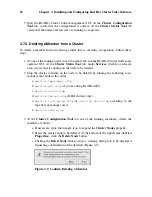
Страница 70: ...be deleted 2 Stop the cluster software on the node to be deleted by running the following com mands at that node in this order a service rgmanager stop b service gfs stop if you are using Red Hat GFS c service clvmd stop d service fenced stop DLM clusters only e service lock_gulmd stop or service cman stop according to the type of lock manager used f service ccsd stop 3 At the Cluster Configuratio...

Страница 71: ...used f service ccsd stop 5 Start cluster software on all remaining cluster nodes including the GULM lock server nodes for a GULM cluster by running the following commands in this order a service ccsd start b service lock_gulmd start or service cman start according to the type of lock manager used c service fenced start DLM clusters only d service clvmd start e service gfs start if you are using Re...

Страница 72: ...ster with several members using a restricted failover domain can minimize the work to set up the cluster to run a cluster service such as httpd which requires you to set up the configuration identically on all members that run the cluster service Instead of setting up the entire cluster to run the cluster service you must set up only the members in the restricted failover domain that you associate...

Страница 73: ...ive to other names used in your cluster Figure 3 10 Failover Domain Configuration Configuring a Failover Domain 4 Click the Available Cluster Nodes drop down box and select the members for this failover domain 5 To restrict failover to members in this failover domain click check the Restrict Failover To This Domains Members checkbox With Restrict Failover To This Domains Members checked services a...

Страница 74: ... the Member Node column having the lowest Priority number 7 Click Close to create the domain 8 At the Cluster Configuration Tool perform one of the following actions depending on whether the configuration is for a new cluster or for one that is operational and running New cluster If this is a new cluster choose File Save to save the changes to the cluster configuration Running cluster If this clus...

Страница 75: ...the cluster configuration Running cluster If this cluster is operational and running and you want to propagate the change immediately click the Send to Cluster button Clicking Send to Cluster automatically saves the configuration change If you do not want to propagate the change immediately choose File Save to save the changes to the cluster configuration 3 8 3 Removing a Member from a Failover Do...

Страница 76: ...he Create a Resource button Clicking the Create a Resource button causes the Resource Configuration dialog box to be displayed 2 At the Resource Configuration dialog box under Select a Resource Type click the drop down box At the drop down box select a resource to configure The resource options are described as follows GFS Name Create a name for the file system resource Mount Point Choose the path...

Страница 77: ... default setting is unchecked Reboot host node if unmount fails If checked reboots the node if un mounting this file system fails The default setting is unchecked Check file system before mounting If checked causes fsck to be run on the file system before mounting it The default setting is unchecked IP Address IP Address Type the IP address for the resource Monitor Link checkbox Check the box to e...

Страница 78: ...rt Name Enter a name for the NFS export resource Script Name Enter a name for the custom user script File with path Enter the path where this custom script is located for ex ample etc init d userscript Samba Service Name Enter a name for the Samba server Work Group Enter the Windows workgroup name or Windows NT domain of the Samba service Note When creating or editing a cluster service connect a S...

Страница 79: ...to be displayed refer to Figure 3 12 Tip Use a descriptive name that clearly distinguishes the service from other services in the cluster Figure 3 12 Adding a Cluster Service 4 If you want to restrict the members on which this cluster service is able to run choose a failover domain from the Failover Domain drop down box Refer to Section 3 8 Configuring a Failover Domain for instructions on how to ...

Страница 80: ...ate the service before restarting Do not restart the node where the service is currently located Disable Do not restart the service at all 8 Click the Add a Shared Resource to this service button and choose the a resource listed that you have configured in Section 3 9 Adding Cluster Resources Note If you are adding a Samba service resource connect a Samba service resource directly to the service n...

Страница 81: ...red_lft forever 3 11 Propagating The Configuration File New Cluster For newly defined clusters you must propagate the configuration file to the cluster nodes as follows 1 Log in to the node where you created the configuration file 2 Using the scp command copy the etc cluster cluster conf file to all nodes in the cluster Note Propagating the cluster configuration file this way is necessary for the ...

Страница 82: ...k manager used 3 service fenced start DLM clusters only 4 service clvmd start 5 service gfs start if you are using Red Hat GFS 6 service rgmanager start 7 Start the Red Hat Cluster Suite management GUI At the Cluster Configuration Tool tab verify that the configuration is correct At the Cluster Status Tool tab verify that the nodes and services are running as expected ...

Страница 83: ...e contents of the etc cluster cluster conf file without guid ance from an authorized Red Hat representative or unless you fully understand the con sequences of editing the etc cluster cluster conf file manually You can access the Cluster Status Tool by clicking the Cluster Management tab at the cluster management GUI to Figure 4 1 Use the Cluster Status Tool to enable disable restart or relocate a...

Страница 84: ...application service status can help identify and resolve problems in the cluster environment The following tools assist in displaying cluster status information The Cluster Status Tool The clustat utility Important Members that are not running the cluster software cannot determine or report the status of other members of the cluster ...

Страница 85: ...g in the node the node appears as a Member in the Cluster Status Tool However without rgmanager running the node does not appear in the clustat display Dead The member system is unable to participate as a cluster member The most basic cluster software is not running on the node Table 4 1 Member Status for the Cluster Status Tool Member Status Description Online The node is communicating with other...

Страница 86: ... disabled Failed The service has failed to start on the cluster and cannot successfully stop the service A failed service is never restarted automatically by the cluster Table 4 3 Service Status The Cluster Status Tool displays the current cluster status in the Services area and au tomatically updates the status every 10 seconds Additionally you can display a snapshot of the current cluster status...

Страница 87: ...service clvmd start 5 service gfs start if you are using Red Hat GFS 6 service rgmanager start To stop the cluster software on a member type the following commands in this order 1 service rgmanager stop 2 service gfs stop if you are using Red Hat GFS 3 service clvmd stop 4 service fenced stop DLM clusters only 5 service lock_gulmd stop or service cman stop according to the type of lock manager use...

Страница 88: ...according the the follow ing steps 1 Make changes to cluster elements for example create a service 2 Propagate the updated configuration file throughout the cluster by clicking Send to Cluster Note The Cluster Configuration Tool does not display the Send to Cluster button if the cluster is new and has not been started yet or if the node from which you are run ning the Cluster Configuration Tool is...

Страница 89: ...le because of misconfiguration restore the configu ration file according to the following steps 1 At the Cluster Configuration Tool tab of the Red Hat Cluster Suite management GUI click File Open 2 Clicking File Open causes the system config cluster dialog box to be displayed 3 At the the system config cluster dialog box select a backup file for example etc cluster cluster conf bak 1 Verify the fi...

Страница 90: ...or information about updating the cluster software contact an authorized Red Hat support representative 4 7 Changing the Cluster Name Although the Cluster Configuration Tool provides a Cluster Properties dialog box with a cluster Name parameter the parameter is intended only for use during initial cluster configuration The only way to change the name of a Red Hat cluster is to create a new cluster...

Страница 91: ...on chkconfig level 2345 cman on chkconfig level 2345 ccsd on You can then reboot the member for the changes to take effect or run the following com mands in the order shown to restart cluster software 1 service ccsd start 2 service lock_gulmd start or service cman start according to the type of lock manager used 3 service fenced start DLM clusters only 4 service clvmd start 5 service gfs start if ...

Страница 92: ...76 Chapter 4 Cluster Administration ...

Страница 93: ...llowing com mand to ensure that the cluster nodes do not automatically start the service when the system boots chkconfig del httpd Rather than having the system init scripts spawn the httpd daemon the cluster infrastruc ture initializes the service on the active cluster node This ensures that the corresponding IP address and file system mounts are active on only one cluster node at a time When add...

Страница 94: ...files that must be in different directories or in separate partitions repeat these steps as needed 5 3 Installing and Configuring the Apache HTTP Server The Apache HTTP Server must be installed and configured on all nodes in the assigned failover domain if used or in the cluster The basic server configuration must be the same on all nodes on which it runs for the service to fail over correctly The...

Страница 95: ...uide 2 The standard Apache HTTP Server start script etc rc d init d httpd is also used within the cluster framework to start and stop the Apache HTTP Server on the active cluster node Accordingly when configuring the service specify this script by adding it as a Script resource in the Cluster Configuration Tool 3 Copy the configuration file over to the other nodes of the cluster or nodes of the fa...

Страница 96: ... HTTP Server service Click Create a Resource Choose IP Address from the drop down menu Enter the IP Address to be associatged with the Apache HTTP Server service Make sure that the Monitor Link checkbox is left checked Click OK 4 Click the Services property 5 Create the Apache HTTP Server service Click Create a Service Type a Name for the service in the Add a Service dialog In the Service Manageme...

Страница 97: ...art discusses the configuration of high performance systems and services with Red Hat Enterprise Linux and LVS This section is licensed under the Open Publication License V1 0 or later For details refer to the Copyright page Table of Contents 6 Introduction to Linux Virtual Server 83 7 Linux Virtual Server Overview 85 8 Initial LVS Configuration 97 9 Setting Up a Red Hat Enterprise Linux LVS Clust...

Страница 98: ......

Страница 99: ...ration Tool a graphical interface used for configuring and monitoring an LVS cluster 6 1 Technology Overview Red Hat Enterprise Linux implements highly available server solutions via clustering It is important to note that cluster computing consists of three distinct branches Compute clustering such as Beowulf uses multiple machines to provide greater com puting power for computationally intensive...

Страница 100: ...2 1 Load Balancing Clusters Using Linux Virtual Servers To an outside user accessing a hosted service such as a website or database application a Linux Virtual Server LVS cluster appears as one server In reality however the user is actually accessing a cluster of two or more servers behind a pair of redundant LVS routers that distribute client requests evenly throughout the cluster system Load bal...

Страница 101: ...n the event of failure 7 1 A Basic LVS Configuration Figure 7 1 shows a simple LVS cluster consisting of two layers On the first layer are two LVS routers one active and one backup Each of the LVS routers has two network interfaces one interface on the Internet and one on the private network enabling them to regulate traffic between the two networks For this example the active router is using Netw...

Страница 102: ... the LVS router to the Internet For instance if eth0 is connected to the Internet than multiple virtual servers can be aliased to eth0 1 Alternatively each virtual server can be associated with a separate device per service For example HTTP traffic can be handled on eth0 1 and FTP traffic can be handled on eth0 2 Only one LVS router is active at a time The role of the active router is to redirect ...

Страница 103: ...re 7 1 is best for clusters serving data which does not change very frequently such as static webpages because the individ ual real servers do not automatically sync data between each node 7 1 1 Data Replication and Data Sharing Between Real Servers Since there is no built in component in LVS clustering to share the same data between the real servers the administrator has two basic options Synchro...

Страница 104: ...e over the network Figure 7 2 A Three Tiered LVS Configuration This configuration is ideal for busy FTP servers where accessible data is stored on a cen tral highly available server and accessed by each real server via an exported NFS directory or Samba share This topography is also recommended for websites that access a central highly available database for transactions Additionally using an acti...

Страница 105: ...rvers using a variety of hardware and software combinations and the active router can evenly load each real server The scheduling mechanism for an LVS cluster is provided by a collection of kernel patches called IP Virtual Server or IPVS modules These modules enable layer 4 L4 transport layer switching which is designed to work well with multiple servers on a single IP ad dress To track and route ...

Страница 106: ...ion scheduling is a better choice Weighted Least Connections default Distributes more requests to servers with fewer active connections relative to their capacities Capacity is indicated by a user assigned weight which is then adjusted upward or downward by dynamic load information The addition of weighting makes this algorithm ideal when the real server pool contains hardware of varying capac ity...

Страница 107: ...ith a weight of 5 gets 5 connections for every 1 connection the other server gets The default value for a real server weight is 1 Although adding weight to varying hardware configurations in a real server pool can help load balance the cluster more efficiently it can cause temporary imbalances when a real server is introduced to the real server pool and the virtual server is scheduled using weight...

Страница 108: ...ting IP address aliased to eth0 1 The NIC for the private network interface has a real IP address on eth1 and has a floating IP address aliased to eth1 1 In the event of failover the virtual interface facing the Internet and the private facing virtual interface are taken over by the backup LVS router simultaneously All of the cluster s real servers located on the private network use the floating I...

Страница 109: ... Examples of such situations include multi screen web forms cookies SSL and FTP connections In these cases a client may not work properly unless the trans actions are being handled by the same server to retain context LVS provides two different features to handle this persistence and firewall marks 7 5 1 Persistence When enabled persistence acts like a timer When a client connects to a service LVS...

Страница 110: ...dd persistence to the virtual servers in conjunction with firewall marks to ensure the clients are reconnected to the same server for an adequate period of time 7 6 LVS Cluster A Block Diagram LVS routers use a collection of programs to monitor cluster members and cluster ser vices Figure 7 4 illustrates how these various programs on both the active and backup LVS routers work together to manage t...

Страница 111: ...lling process which starts all other daemons related to LVS routers At boot time the daemon is started by the etc rc d init d pulse script It then reads the configuration file etc sysconfig ha lvs cf On the active router pulse starts the LVS daemon On the backup router pulse determines the health of the active router by executing a simple heartbeat at a user configurable interval If the active rou...

Страница 112: ...rectly all daemons get their con figuration information from this file 7 6 1 6 Piranha Configuration Tool This is the Web based tool for monitoring configuring and administering an LVS clus ter This is the default tool to maintain the etc sysconfig ha lvs cf LVS cluster configuration file 7 6 1 7 send_arp This program sends out ARP broadcasts when the floating IP address changes from one node to a...

Страница 113: ... of the components needed to set up an LVS cluster but the appropriate services must be activated before configuring the cluster For both LVS routers set the appropriate services to start at boot time There are three primary tools available for setting services to activate at boot time under Red Hat Enterprise Linux the command line program chkconfig the ncurses based program ntsysv and the graphi...

Страница 114: ...e Section 8 3 Starting the Piranha Configuration Tool Service for an example of how to use the sbin service command For more information on runlevels and configuring services with ntsysv and the Services Configuration Tool refer to the chapter titled Controlling Access to Services in the Red Hat Enterprise Linux System Administration Guide 8 2 Setting a Password for the Piranha Configuration Tool ...

Страница 115: ... version of httpd runs as the piranha user in a separate process The fact that piranha gui leverages the httpd service means that 1 The Apache HTTP Server must be installed on the system 2 Stopping or restarting the Apache HTTP Server via the service command stops the piranha gui service Warning If the command sbin service httpd stop or sbin service httpd restart is is sued on an LVS router you mu...

Страница 116: ...ccomplish this task 8 4 Limiting Access To the Piranha Configuration Tool The Piranha Configuration Tool prompts for a valid username and password combina tion However because all of the data passed to the Piranha Configuration Tool is in plain text it is recommended that you restrict access only to trusted networks or to the local machine The easiest way to restrict access is to use the Apache HT...

Страница 117: ...cket Forwarding In order for the LVS router to forward network packets properly to the real servers each LVS router node must have IP forwarding turned on in the kernel Log in as root and change the line which reads net ipv4 ip_forward 0 in etc sysctl conf to the following net ipv4 ip_forward 1 The changes take effect when you reboot the system To check if IP forwarding is turned on issue the foll...

Страница 118: ...102 Chapter 8 Initial LVS Configuration It may also be useful to access the real servers remotely so the sshd daemon should also be installed and running ...

Страница 119: ...tilizing NAT routing is the easiest to configure from a network layout perspective because the cluster needs only one access point to the public network The real servers pass all requests back through the LVS router so they are on their own private network Hardware The NAT topography is the most flexible in regards to cluster hardware because the real servers do not need to be Linux machines to fu...

Страница 120: ...TO static ONBOOT yes IPADDR 192 168 26 9 NETMASK 255 255 255 0 GATEWAY 192 168 26 254 The etc sysconfig network scripts ifcfg eth1 for the private NAT interface on the LVS router could look something like this DEVICE eth1 BOOTPROTO static ONBOOT yes IPADDR 10 11 12 9 NETMASK 255 255 255 0 In this example the VIP for the LVS router s public interface will be 192 168 26 10 and the VIP for the NAT or...

Страница 121: ...ping or connect in other ways to the public network This is normal You will however be able to ping the real IP for the LVS router s private interface in this case 10 11 12 8 So the real server s etc sysconfig network scripts ifcfg eth0 file could look similar to this DEVICE eth0 ONBOOT yes BOOTPROTO static IPADDR 10 11 12 1 NETMASK 255 255 255 0 GATEWAY 10 11 12 10 Warning If a real server has mo...

Страница 122: ...n Tool Warning Do not configure the floating IP for eth0 1 or eth1 1 by manually editing network scripts or using a network configuration tool Instead use the Piranha Configuration Tool as shown in Section 10 4 GLOBAL SETTINGS and Section 10 6 1 The VIRTUAL SERVER Subsection to configure any cluster related virtual interfaces When finished start the pulse service as shown in Section 10 8 Starting ...

Страница 123: ...configure the cluster using the Piranha Configuration Tool The sections on each topography give example network addresses but the actual network ad dresses are needed Below are some useful commands for bringing up network interfaces or checking their status Bringing Up Real Network Interfaces The best way to bring up any real network interface is to use the following commands as root replacing N w...

Страница 124: ...etwork packet filter iptables outside of Piranha Configuration Tool 9 3 1 Assigning Firewall Marks To assign firewall marks to a packet destined for a particular port the administrator must use iptables This section illustrates how to bundle HTTP and HTTPS as an example however FTP is another commonly clustered multi port protocol If an LVS cluster is used for FTP services see Section 9 4 FTP In a...

Страница 125: ...ffect immediately but do not persist through a reboot of the system To ensure network packet filter settings are restored upon reboot refer to Section 9 5 Saving Network Packet Filter Settings 9 4 FTP In an LVS Cluster File Transport Protocol FTP is an old and complex multi port protocol that presents a distinct set of challenges to a clustered environment To understand the nature of these challen...

Страница 126: ...open a large number of ports that the Piranha Configuration Tool and IPVS do not know about 9 4 2 How This Affects LVS Routing IPVS packet forwarding only allows connections in and out of the cluster based on it recognizing its port number or its firewall mark If a client from outside the cluster attempts to open a port IPVS is not configured to handle it drops the connection Similarly if the real...

Страница 127: ...connections com ing in from the Internet to the floating IP for the service on a wide range of ports 10 000 to 20 000 Warning If you are limiting the port range for passive connections you must also configure the VSFTP server to use a matching port range This can be accomplished by adding the following lines to etc vsftpd conf pasv_min_port 10000 pasv_max_port 20000 You must also control the addre...

Страница 128: ... Packet Filter Settings Finally you need to be sure that the appropriate service is set to activate on the proper runlevels For more on this refer to Section 8 1 Configuring Services on the LVS Routers 9 5 Saving Network Packet Filter Settings After configuring the appropriate network packet filters for your situation save the settings so they get restored after a reboot For iptables type the foll...

Страница 129: ...9 Setting Up a Red Hat Enterprise Linux LVS Cluster 113 The next chapter explains how to use the Piranha Configuration Tool to configure the LVS router and describe the steps necessary to active an LVS cluster ...

Страница 130: ...114 Chapter 9 Setting Up a Red Hat Enterprise Linux LVS Cluster ...

Страница 131: ...achine you also need an ssh connection to the primary LVS router as the root user While configuring the primary LVS router it is a good idea to keep a concurrent ssh con nection in a terminal window This connection provides a secure way to restart pulse and other services configure network packet filters and monitor var log messages during trouble shooting The next four sections walk through each ...

Страница 132: ...Tool is made of four main screens or panels In addition the Virtual Servers panel contains four subsections The CONTROL MONITORING panel is the first panel after the login screen 10 3 CONTROL MONITORING The CONTROL MONITORING Panel presents the cluster administrator with a limited runtime status of the cluster It displays the status of the pulse daemon the LVS routing table and the LVS spawned nan...

Страница 133: ...lick on the Auto update checkbox and set the desired update frequency in the Update frequency in seconds text box the default value is 10 seconds It is not recommended that you set the automatic update to an interval less than 10 seconds Doing so may make it difficult to reconfigure the Auto update interval be cause the page will update too frequently If you encounter this issue simply click on an...

Страница 134: ...the status information manually by clicking this button CHANGE PASSWORD Clicking this button takes you to a help screen with information on how to change the administrative password for the Piranha Configuration Tool 10 4 GLOBAL SETTINGS The GLOBAL SETTINGS panel is where the cluster administrator defines the networking details for the primary LVS router s public and private network interfaces ...

Страница 135: ...publicly routable real IP address for the primary LVS node Primary server private IP Enter the real IP address for an alternative network interface on the primary LVS node This address is used solely as an alternative heartbeat channel for the backup router and does not have to correlate to the real private IP address assigned in Section 9 1 1 Configuring Network Interfaces for a NAT LVS Cluster Y...

Страница 136: ...y for the real servers NAT Router netmask If the NAT router s floating IP needs a particular netmask select it from drop down list NAT Router device Use this text field to define the device name of the network interface for the floating IP address such as eth1 1 Tip You should alias the NAT floating IP address to the Ethernet interface connected to the private network In this example the private n...

Страница 137: ...isit this screen it displays an inactive Backup status and an ENABLE button To configure the backup LVS router click on the ENABLE button so that the screen matches Figure 10 4 Figure 10 4 The REDUNDANCY Panel Redundant server public IP Enter the public real IP address for the backup LVS router node ...

Страница 138: ... primary LVS node Assume dead after seconds If the primary LVS node does not respond after this number of seconds then the backup LVS router node will initiate failover Heartbeat runs on port This field sets the port at which the heartbeat communicates with the primary LVS node The default is set to 539 if this field is left blank Warning Remember to click the ACCEPT button after making any change...

Страница 139: ...he virtual server and click the DELETE button To enable or disable a virtual server in the table click its radio button and click the DE ACTIVATE button After adding a virtual server you can configure it by clicking the radio button to its left and clicking the EDIT button to display the VIRTUAL SERVER subsection 10 6 1 The VIRTUAL SERVER Subsection The VIRTUAL SERVER subsection panel shown in Fig...

Страница 140: ...CEPT button Figure 10 6 The VIRTUAL SERVERS Subsection Name Enter a descriptive name to identify the virtual server This name is not the hostname for the machine so make it descriptive and easily identifiable You can even reference the protocol used by the virtual server such as HTTP Application port Enter the port number through which the service application will listen Since this example is for ...

Страница 141: ... state Warning Entering a firewall mark in this field allows IPVS to recognize that packets bearing this firewall mark are treated the same but you must perform further configuration outside of the Piranha Configuration Tool to actually assign the firewall marks See Section 9 3 Multi port Services and LVS Clustering for instructions on creating multi port services and Section 9 4 FTP In an LVS Clu...

Страница 142: ...ned with weighted scheduling algorithms Also if you use load monitoring the real servers in the cluster must be Linux machines Scheduling Select your preferred scheduling algorithm from the drop down menu The default is Weighted least connection For more information on scheduling algo rithms see Section 7 3 1 Scheduling Algorithms Persistence If an administrator needs persistent connections to the...

Страница 143: ...relation to firewall marks to achieve the same result Warning Remember to click the ACCEPT button after making any changes in this panel To make sure you do not lose changes when selecting a new panel 10 6 2 REAL SERVER Subsection Clicking on the REAL SERVER subsection link at the top of the panel displays the EDIT REAL SERVER subsection It displays the status of the physical server hosts for a pa...

Страница 144: ...uration Tool Figure 10 7 The REAL SERVER Subsection Click the ADD button to add a new server To delete an existing server select the radio button beside it and click the DELETE button Click the EDIT button to load the EDIT REAL SERVER panel as seen in Figure 10 8 ...

Страница 145: ...This panel consists of three entry fields Name A descriptive name for the real server Tip This name is not the hostname for the machine so make it descriptive and easily identifiable Address The real server s IP address Since the listening port is already specified for the asso ciated virtual server do not add a port number ...

Страница 146: ...ember to click the ACCEPT button after making any changes in this panel To make sure you do not lose any changes when selecting a new panel 10 6 3 EDIT MONITORING SCRIPTS Subsection Click on the MONITORING SCRIPTS link at the top of the page The EDIT MONI TORING SCRIPTS subsection allows the administrator to specify a send expect string sequence to verify that the service for the virtual server is...

Страница 147: ...elpful for services that require dynamically changing data such as HTTPS or SSL To use this functionality you must write a script that returns a textual response set it to be executable and type the path to it in the Sending Program field Tip To ensure that each server in the real server pool is checked use the special token h after the path to the script in the Sending Program field This token is...

Страница 148: ...field blank the nanny daemon attempts to open the port and assume the service is running if it succeeds Only one send sequence is allowed in this field and it can only contain printable ASCII characters as well as the following escape characters n for new line r for carriage return t for tab to escape the next character which follows it Expect Enter a the textual response the server should return ...

Страница 149: ...lude etc sysconfig ha lvs cf the configuration file for the LVS routers etc sysctl the configuration file that among other things turns on packet for warding in the kernel etc sysconfig iptables If you are using firewall marks you should synchro nize one of these files based on which network packet filter you are using Important The etc sysctl conf and etc sysconfig iptables files do not change wh...

Страница 150: ...e is read at boot time and tells the kernel to turn on packet forwarding Important If you are not sure whether or not packet forwarding is enabled in the kernel see Section 8 5 Turning on Packet Forwarding for instructions on how to check and if necessary enable this key functionality 10 7 3 Synchronizing Network Packet Filtering Rules If you are using iptables you will need to synchronize the app...

Страница 151: ...ail f var log messages Then start the cluster by typing the following command into the other terminal sbin service pulse start Follow the progress of the pulse service s startup in the terminal with the kernel log messages When you see the following output the pulse daemon has started properly gratuitous lvs arps finished To stop watching var log messages type Ctrl c From this point on the primary...

Страница 152: ...136 Chapter 10 Configuring the LVS Routers with Piranha Configuration Tool ...

Страница 153: ...Free Documentation License For details refer to the Copyright page Table of Contents A Supplementary Hardware Information 139 B Selectively Installing Red Hat Cluster Suite Packages 147 C Multipath usage txt File for Red Hat Enterprise Linux 4 Update 3 157 ...

Страница 154: ......

Страница 155: ...bus Single initiator interconnects ensure that each node is protected from disruptions due to the work load initialization or repair of the other node If employing a RAID array that has multiple host ports and the RAID array provides simultaneous access to all the shared logical units from the host ports on the storage enclo sure set up single initiator Fibre Channel interconnects to connect each ...

Страница 156: ... RAID array use a Fibre Channel hub or switch In this case each host bus adapter is connected to the hub or switch and the hub or switch is connected to a host port on the RAID controller A Fibre Channel hub or switch is also required with a dual controller RAID array with two host ports on each controller This configuration is shown in Figure A 2 Additional cluster nodes may be connected to eithe...

Страница 157: ...ous access to all the shared logical units from the host ports on the storage enclosure the setup of the single initiator SCSI buses to connect each cluster node to the RAID array is possible If a logical unit can fail over from one controller to the other the process must be transparent to the operating system Note that some RAID controllers re strict a set of disks to a specific controller or po...

Страница 158: ...on refer to the vendor documentation Figure A 3 shows a configuration that uses two single initiator SCSI buses Figure A 3 Single initiator SCSI Bus Configuration Figure A 4 shows the termination in a single controller RAID array connected to two single initiator SCSI buses Figure A 4 Single controller RAID Array Connected to Single initiator SCSI Buses Figure A 5 shows the termination in a dual c...

Страница 159: ...ters and disks on a bus must have unique SCSI identification numbers Refer to Section A 3 4 SCSI Identification Numbers for more information The Linux device name for each shared SCSI device must be the same on each cluster system For example a device named dev sdc on one cluster system must be named dev sdc on the other cluster system One way to ensure that devices are named the same is by using ...

Страница 160: ...e initiator bus first disconnect the SCSI cable from the RAID controller and then from the adapter This ensures that the RAID controller is not exposed to any erroneous input Protect connector pins from electrostatic discharge while the SCSI cable is disconnected by wearing a grounded anti static wrist guard and physically protecting the cable ends from contact with other objects Do not remove a d...

Страница 161: ...ity order to assign SCSI identification numbers 7 6 5 4 3 2 1 0 15 14 13 12 11 10 9 8 The previous order specifies that 7 is the highest priority and 8 is the lowest priority The default SCSI identification number for a host bus adapter is 7 because adapters are usually assigned the highest priority It is possible to assign identification numbers for logical units in a RAID subsystem by using the ...

Страница 162: ...146 Appendix A Supplementary Hardware Information ...

Страница 163: ...anager CMAN which is used for managing cluster membership messaging and notification cman kernel Contains required CMAN kernel modules dlm Contains distributed lock management DLM library dlm kernel Contains required DLM kernel modules fence The cluster I O fencing system that allows cluster nodes to connect to a variety of network power switches fibre channel switches and integrated power managem...

Страница 164: ...ce For more information on using Red Hat Network visit the following URL http rhn redhat com You can install Red Hat Cluster Suite and Red Hat GFS RPMs using either of the following methods Automatic RPM installation Using up2date Custom RPM installation Selectively installing RPMs using the rpm utility For automatic RPM installation refer to Section B 1 1 Automatic RPM Installation For custom RPM...

Страница 165: ... refer to Section B 1 2 1 Determining RPMs To Install 2 Install the RPMs using the rpm utility For information about installing the RPMs using the rpm utility refer to Section B 1 2 2 Installing Packages with the rpm Utility Note If you are installing the GFS RPMs you must install Red Hat Cluster Suite before Red Hat GFS B 1 2 1 Determining RPMs To Install Determining which RPMs to install is base...

Страница 166: ... a concise description of the RPM purpose Assists in determining which RPMs to include other than the required RPMs To determine which RPMs to include in the installation perform the following steps 1 Determine whether you are installing Red Hat Cluster Suite with DLM or Red Hat Cluster Suite with GULM a If you are installing Red Hat Cluster Suite with DLM refer to Table B 1 to identify which RPMs...

Страница 167: ...r rel arch dlm kernel smp ver rel arch Note The types of RPMs available vary according to RHN channel Req Yes The Distributed Lock Manager kernel modules fence ver rel arch Req No The cluster I O fencing system iddev ver rel arch Req No A library that identifies device contents magma ver rel arch Req No A cluster lock manager API abstraction library magma plugins ver rel arch Req No Cluster manage...

Страница 168: ...irtual Server piranha ver rel arch Opt No Cluster administration tools ccs devel ver rel arch Dev No CCS static library cman kernheaders ver rel arch Dev No cman kernel header files dlm devel ver rel arch Dev No The Distributed Lock Manager user space libraries dlm kernheaders ver rel arch Dev No dlm kernel header files iddev devel ver rel arch Dev No iddev development libraries magma devel ver re...

Страница 169: ...t identifies device contents magma ver rel arch Req No A cluster lock manager API abstraction library magma plugins ver rel arch Req No Cluster manager plugins for magma perl Net Telnet ver rel arch Req No Net Telnet Perl module system config cluster ver rel arch Req No GUI to manage cluster configuration ipvsadm ver rel arch Opt No Utility to administer the Linux Virtual Server piranha ver rel ar...

Страница 170: ...mp ver rel arch Note The types of RPMs available vary according to RHN channel Req Yes The Red Hat GFS kernel modules gnbd ver rel arch Opt No The GFS Network Block Device gnbd kernel ver rel arch gnbd kernel hugemem ver rel arch gnbd kernel smp ver rel arch Note The types of RPMs available vary according to RHN channel Opt Yes Kernel module for GFS Network Block Device lvm2 cluster ver rel arch R...

Страница 171: ... run autorun click No 3 Copy all the RPM files from the CD located in media cdrom RedHat RPMS to the temporary directory created earlier For example cp media cdrom RedHat RPMS rpm tmp RPMS Note If your local computer is running a version of Red Hat Enterprise Linux that is earlier than Red Hat Enterprise Linux 4 the path to the RPMs on the CD may be different For example on Red Hat Enterprise Linu...

Страница 172: ...l or development RPMS The following example removes SMP and hugemem kernel RPM files rm kernel smp kernel hugemem For information about selecting the RPMs to install refer to Section B 1 2 1 Deter mining RPMs To Install 10 Log in to each cluster node as the root user and make a directory to contain the RPMs For example mkdir tmp node RPMS 11 Copy the RPMs from the temporary directory in the local ...

Страница 173: ...ttached to a storage controller with two ports via a single unzoned FC switch sees four devices dev sda dev sdb dev sdc and dev sdd DM MP creates a single device dev mpath mpath1 that reroutes I O to those four underlying devices DM MP consists of the following components o dm multipath kernel module This module reroutes I O and fails over paths and path groups o multipath command This command con...

Страница 174: ...TP9100 o SGI TP9300 o SGI TP9400 o SGI TP9500 o STK OPENstroage D280 o SUN StorEdge 3510 o SUN T4 Storage arrays not included in the list may require entries in the etc multipath conf file NOTE Some storage arrays require special handling of I O errors and path group switching Those require separate hardware handler kernel modules Terms and Concepts Hardware Handler A kernel module that performs h...

Страница 175: ...he active state NOTE The disabled state only exists for certain storage arrays Path Priority Each path can have a priority assigned to it by a callout program Path priorities can be used to group paths by priority and change their relative weights for the round robin path selector Path Group Priority Each path group has a priority that is equal to the sum of the priorities of all the non faulty pa...

Страница 176: ... alias is set to the WWID However by setting the user_friendly_names configuration option the alias is set to a unique name of the form mpath n The alias name can also be explicitly set for each multipath device in the configuration file NOTE While the alias in guaranteed to be unique on a node it is not guaranteed to be the same on all nodes using the multipath device Also it may change WWID The ...

Страница 177: ... After initial setup all access to the multipathed storage should go through the multipath device Configuration File Many features of DM MP are configurable using the configuration file etc multipath conf For a complete list of all options with descriptions refer to usr share doc device mapper multipathd 0 4 5 multipath conf annotated The configuration file is divided into four sections system def...

Страница 178: ...lows For each multipath device action_if_any alias wwid_if_different_from_alias size features hardware_handler For each path group _ scheduling_policy path_group_priority_if_known path_group_status_if_known For each path _ host channel id lun devnode major minor path_status dm_status_if_known NOTE The preceding lines for path group and path were broken because of print limitations The dm status dm...

Страница 179: ...explanation usr share doc device mapper multipathd 0 4 5 multipath conf annotated Upstream documentation http christophe varoqui free fr wiki wakka php wiki Home mailing list dm devel redhat com Subscribe to this from https www redhat com mailman listinfo dm devel The list archives are at https www redhat com archives dm devel Man pages multipath 8 multipathd 8 kpartx 8 mpath_ctl 8 ...

Страница 180: ...164 Appendix C Multipath usage txt File for Red Hat Enterprise Linux 4 Update 3 ...

Страница 181: ... 73 starting and stopping the cluster software 71 updating the cluster software 74 cluster configuration minimum example 10 modifying 71 Cluster Configuration Tool accessing 38 cluster database backing up 73 restoring 73 cluster hardware connecting 27 fence devices 14 setting up 27 cluster hardware tables 14 cluster node hardware table 14 cluster service displaying status 68 cluster service manage...

Страница 182: ...nfiguration 10 no single point of failure configuration 13 ext3 34 F feedback vi fence device configuring 30 fence devices 14 network attached 14 serial attached 14 watchdog timers 14 hardware based 14 software based 14 file systems creating 34 FTP clustering 109 See Also LVS clustering G GFS software subsystem components table 5 H hardware installing basic cluster hardware 19 hardware configurati...

Страница 183: ...rs 87 definition of 83 initial configuration 97 ipvsadm program 95 job scheduling 89 lvs daemon 95 LVS routers configuring services 97 necessary services 97 primary node 97 multi port services 108 FTP 109 nanny daemon 96 NAT routing enabling 106 requirements hardware 103 requirements network 103 requirements software 103 overview of 84 85 packet forwarding 101 Piranha Configuration Tool 96 pulse d...

Страница 184: ...25 Persistence 126 Scheduling 126 Virtual IP Address 125 VIRTUAL SERVER subsection 123 VIRTUAL SERVERS 122 piranha gui service 97 piranha passwd 98 power controller connection configuring 45 power switch 45 See Also power controller pulse daemon 95 pulse service 97 R real servers See LVS clustering configuring services 101 Red Hat Cluster Manager 83 subsystem 4 Red Hat Cluster Suite 39 147 custom ...

Страница 185: ...ole switch hardware 18 GFS software subsystem components 5 installing the basic cluster hardware 19 member status for Cluster Status Tool 69 member status forclustat 69 minimum cluster configuration components 11 network hardware 16 no single point of failure configuration 13 power controller connection configuring 45 Red Hat Cluster Suite DLM RPM selection criteria 150 Red Hat Cluster Suite GULM ...

Страница 186: ......

Страница 187: ...Red Hat Enterprise Linux Introduc tion to System Administration Primary Writer Maintainer of the Release Notes Contribut ing Writer to the Red Hat Enterprise Linux Installation Guide for x86 Itanium AMD64 and Intel Extended Memory 64 Technology Intel EM64T Karsten Wade Primary Writer Maintainer of the Red Hat SELinux Guide Contributing Writer to the Red Hat Enterprise Linux System Administration G...

Страница 188: ...itza Louze Spanish translations Noriko Mizumoto Japanese translations Ankitkumar Rameshchandra Patel Gujarati translations Rajesh Ranjan Hindi translations Nadine Richter German translations Audrey Simons French translations Francesco Valente Italian translations Sarah Wang Simplified Chinese translations Ben Hung Pin Wu Traditional Chinese translations Tongjie Tony Fu Simplified Chinese Translati...

Отзывы: