A-1
INSTALLATION
MEGA FORCE
®
140i MP
®
INSTALLATION
TECHNICAL SPECIFICATIONS -
*Max wire feed speed achieved with a spool gun
Thermal tests have been performed at ambient temperature. The duty
cycle (duty factor) at 40°C has been determined by simulation.
select sUitable location
Place the machine on a secure, level surface or recommended
undercarriage. The machine may topple over if this procedure is
not followed. To minimize over heating, locate the welder in a dry
location where there is free circulation of clean air. Do not place
on combustible surfaces.
The machine is capable of higher duty cycles at lower output
currents or higher amperages at lower duty cycles. An overview
of the machine’s input and output capabilities are available on the
rating plate located on the back of the machine.
location anD MoUntinG
The welding machine will operate in harsh environments. Even so,
it is important that preventative measures are followed in order to
assure long life, reliability, and safe operation.
•
The welding machine must be located in an area with
circulation of clean air such that air moves in the back of the
machine and out the front louvers.
•
Dirt and dust that can be drawn into the welding machine
should be kept to a minimum. Failure to observe these
precautions can result in excessive operating temperatures,
nuisance thermal trips and potential failures.
environMental ratinG
The welding power source carries an IP21S rating. It may be used
in normal industrial and commercial environments. Avoid using in
areas where water / rain is present.
Read and follow the ‘Electric Shock Warnings’ in the safety section
if welding must be performed under electrically hazardous
conditions such as welding in wet areas or water on the work
piece.
enGine Driven Generator
The machine is designed to operate on engine driven generators as
long as the auxiliary can supply adequate voltage, frequency and
power as indicated in the “Technical Specification” Installation
Section of this manual. The auxiliary supply of the generator must
also meet the following conditions:
Frequency:
60 Hz
RMS voltage of the AC waveform:
90-140 V; Out of this range will
trigger undervoltage and overvoltage protections.
Generator Minimum
6 kW
It is important to check these conditions because many engine driven
generators produce high voltage spikes. Operation of this machine
with engine driven generators not conforming to these conditions is
not recommend and may damage the machine and is also NOT
covered by warranty.
INPUT VOLTAGE AND CURRENT
Duty Cycle
(Output)
Input Voltage Input Amperes
Max
Idle Amps
60% FOR MIG
120 V~
20 A
.7A
RECOMMENDED INPUT WIRE AND FUSE SIZES
Voltage/Phase/
Frequency
Input Amperes
Effective
Fuse (Super Lag) or
Breaker Size
120/1/60Hz
15 A
20 A
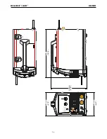
PHYSICAL DIMENSIONS
Height
Width
Depth
Weight
13.6”
(345mm)
8.9”
(224mm)
18.1”
(460mm)
34.5 lbs.
(15.6 kg)
WELDING PROCESSES
Process
Electrode Diameter
Range
Output Range
(Amperes)
Wire Feed
Speed Range
MIG
.025-.035”
( 0.6-0.9mm)
20-140
40-500* IPM
FCAW
.030-.035”
(0.8-0.9mm)
20-140
40-400 IPM
TIG
.040, 1/16, 3/32”
(1.0, 1.6MM, 2.4mm)
10-120
NA
STICK
Up to 3/32”
(2.4mm)
25-90
NA
TEMPERATURE RANGES
Operating
Temperature
-4°F TO 104°F (-20°C TO 40°C)
Storage
Temperature
-40°F TO 185°F (-40°C TO 85°C)
WELDING PROCESSES
Process
Duty Cycle
Amperage
Voltage
MIG & FCAW
60%
95 AMPS
18.75 VOLTS
TIG
60%
115 AMPS
14.6 VOLTS
STICK
60%
80 AMPS
23.2 VOLTS
REGULATORY REQUIREMENTS
Market
Conformity Mark
Standard
MÉXICO
NOM
NMX-J-038-1
ANSE 2016
Содержание Mega Force 140i MP
Страница 23: ...F 4 DIAGRAMS MEGA FORCE 140i MP MM MM MM MM ...


